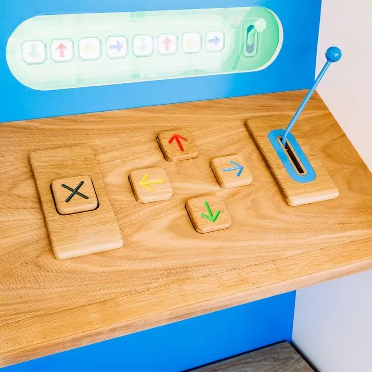
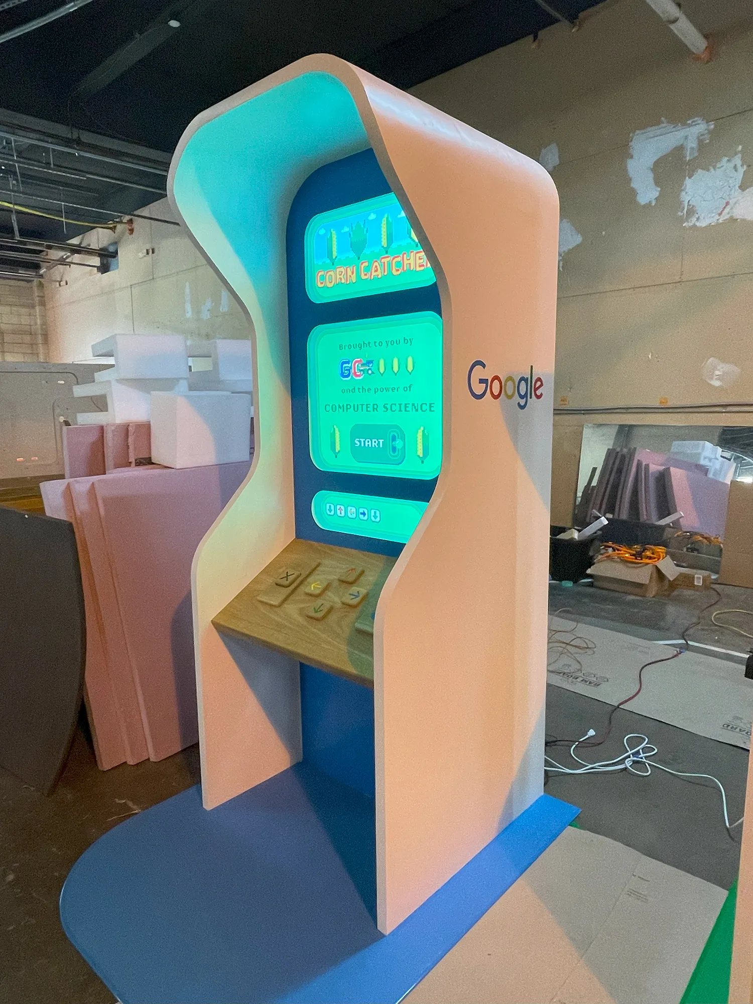
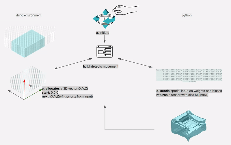
takes a 3D sketch done in AR space using a hand held mobile phone, to predict and reconstruct a mesh of the corresponding sketch that is displayed back into the AR space. The model leverages the complementary affordances of 3D sketching (immersive, unconstrained, life-sized) and pretrained ML models (precise, constrained, ergonomic) interactions and tools for in situ 3D prototyping.
The applications of AR in design have been growing beyond visualization into a collaborative space of collective intelligence between human and AI. Interactive interfacing between designers and the three dimensional tools at the early stages of design ideation reduces the friction of rapid design prototyping. Developments in motion tracking algorithms allow real-time tracking of mobile devices, and therefore enable access to 3D mid-air sketching in Augmented Reality (AR). We utilize 3D GAN, recent model that generates 3D objects from a probabilistic space, as a method of of exploring a design space that interpolates between various objects at the scale of furniture to develop a model that generalizes mesh geometries from 3D sketches. In this research, we present a novel algorithmic workflow for data preparation and processing for 3D Sketch - Mesh pairs, and use a Multi-layer Perceptron (MLP) based regression for mesh reconstruction. We also present a frontend AR drawing application, with a user-sketch processing workflow to reconstruct meshes in-place in AR. Through this research, we also show that this approach is modular, easy to deploy, and robust to style changes. ARSketchNet takes a 3D sketch done in AR space using a hand held mobile phone, to predict and reconstruct a mesh of the corresponding sketch that is displayed back into the AR space. The model leverages the complementary affordances of 3D sketching (immersive, unconstrained, life-sized) and pretrained ML models (precise, constrained, ergonomic) interactions and tools for in situ 3D prototyping.
A new era of human-computer interaction is folding with advances in tools that augment human capabilities and creative workflows. Information expression in twodimensional space provides a limited mode of prototyping in creative spatial design. Augmented Reality (AR) accompanies designers by bringing virtual information not only to their immediate surroundings in real-time, but also to any indirect view of the real world environment. While AR was used mainly to enhance the user’s ability to visualize and interact with the real world, today AR merged with AI capabilities could be part of a collective intelligence where a collaborative design process between man and machine exists.

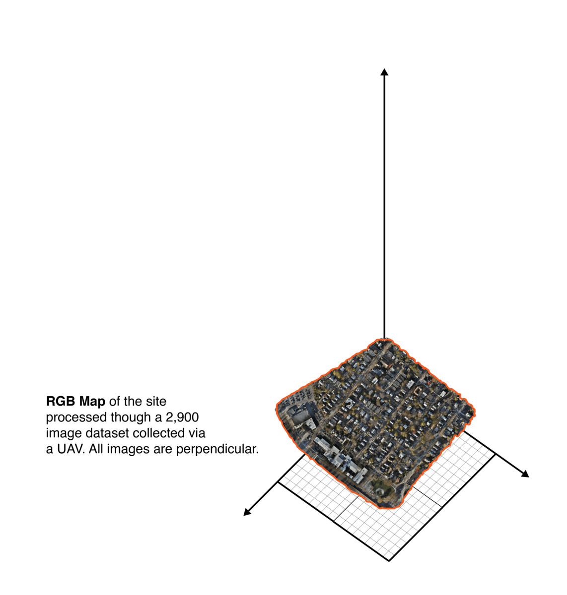
Processed information from the flight to ensure dataset quality, errors due to excessive motion and flight path information such as areas, heights, GPS information..etc.
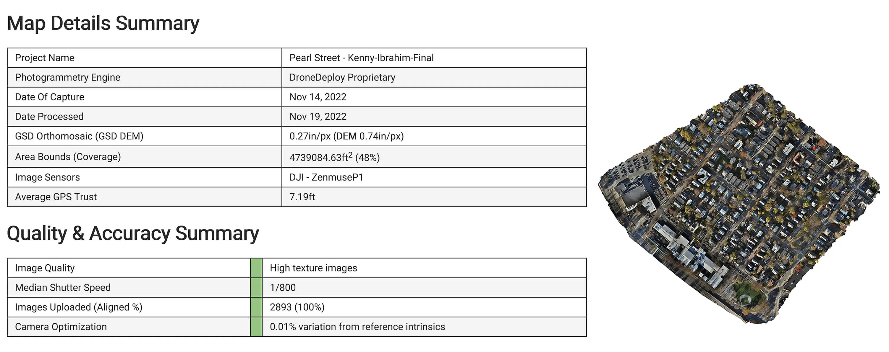
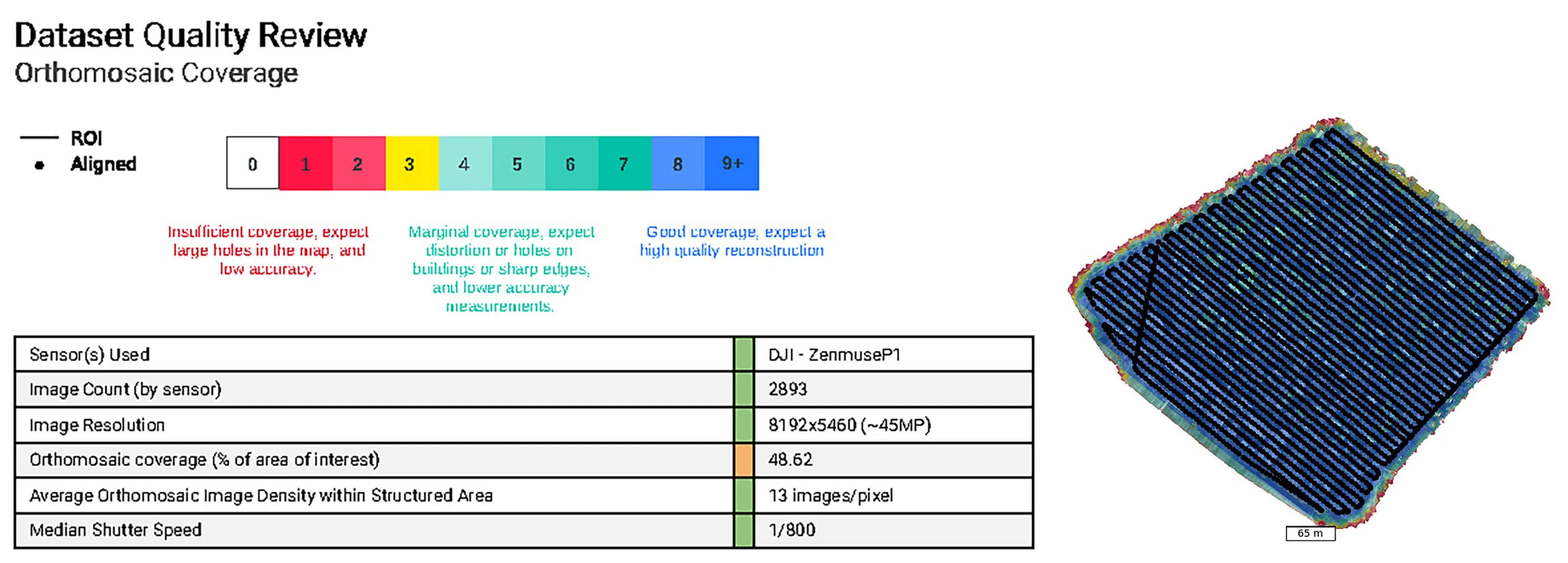
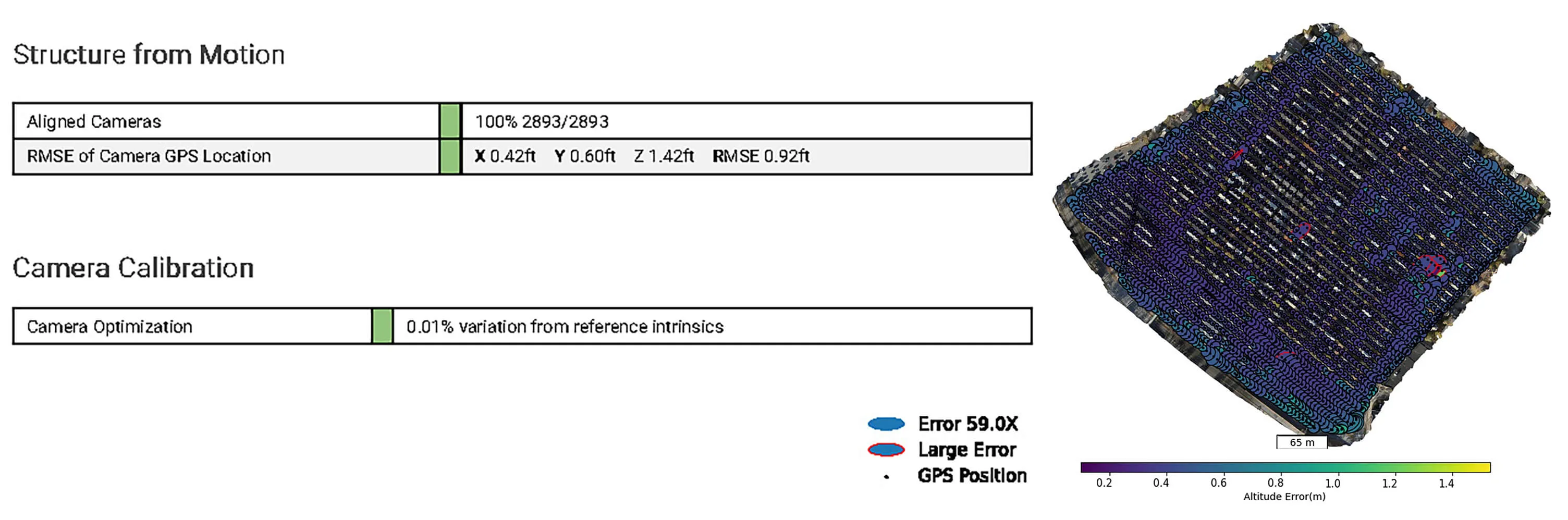
Looked at different map information to extract useful input for our site simulator and agent ML training.
The application and interface developed on Unity includes:
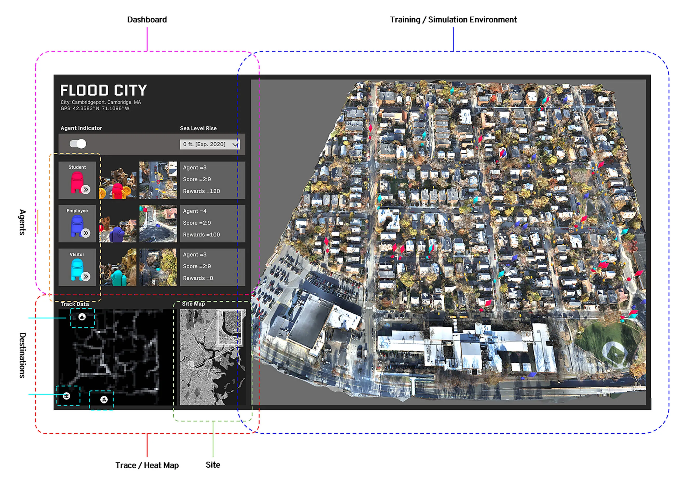
Ray Perception Sensor 3D, aperception sensor that returns a compressed representation of the observation:obstacle (positive / red), void (negative / white).
Through trial and error, we learntthat enabling the agent with multiple perception sensor enhanced the trainingresults.
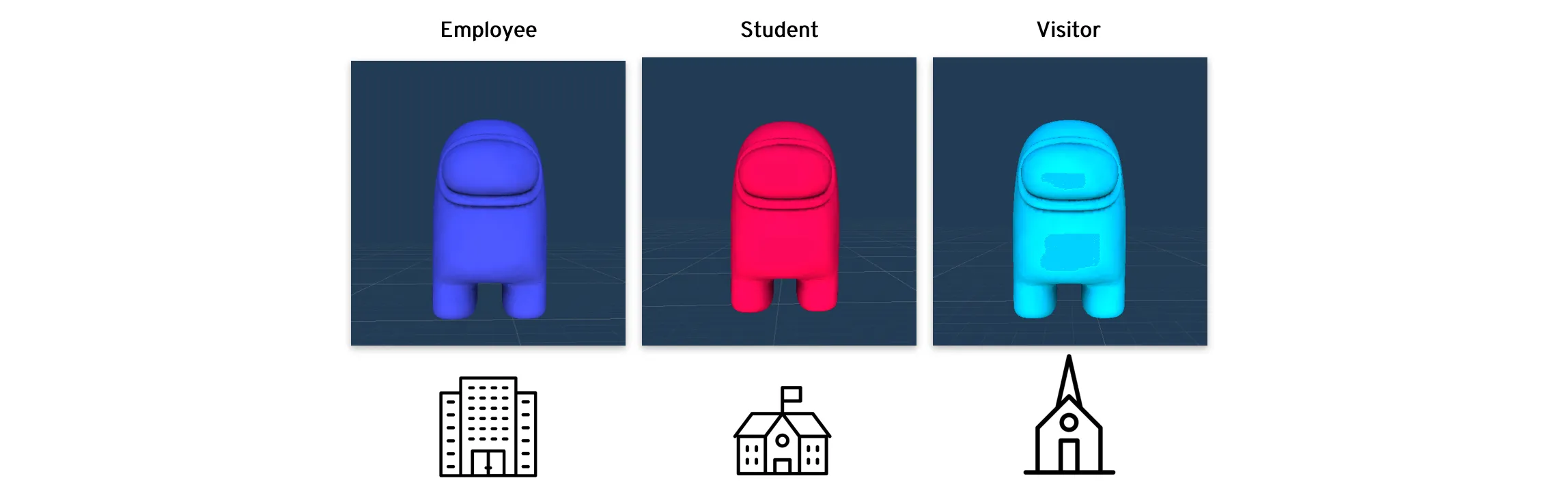
NPC: Non-Player Character
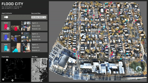
ML trained simulations on several scenarios:
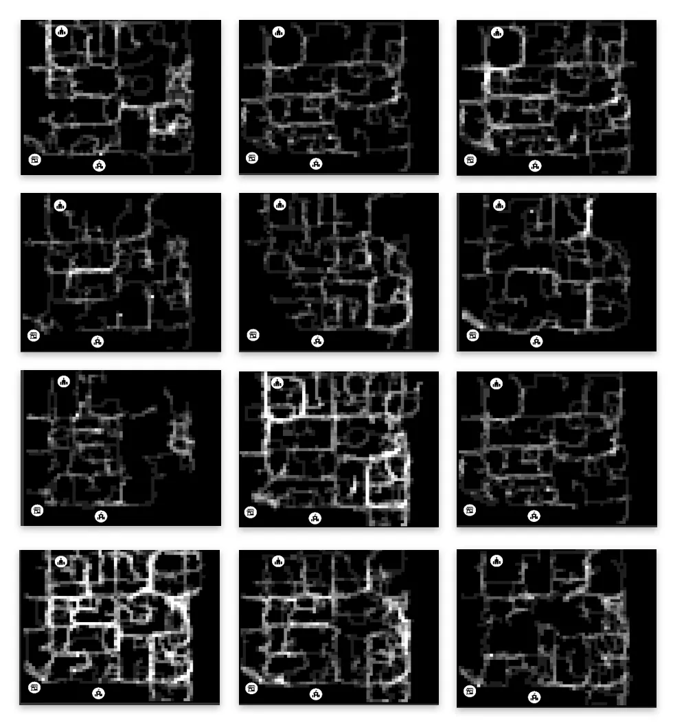
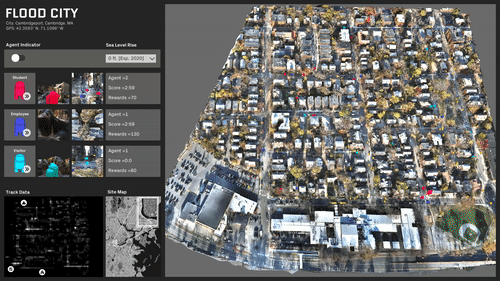
Travel behavior and paths is almost evenly distributed.
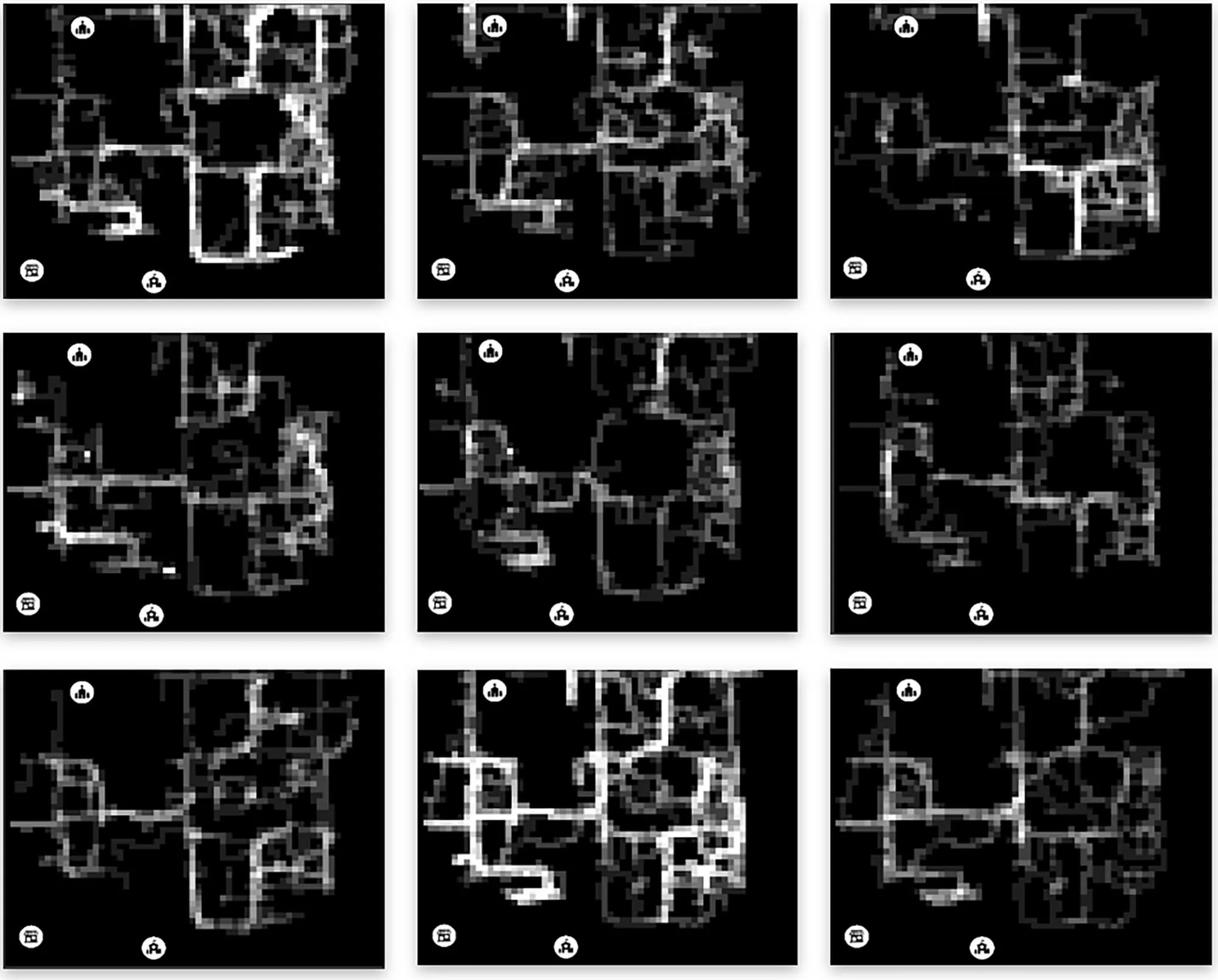
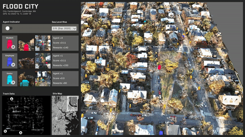
A specific area in the center of the site is rendered inaccessible.
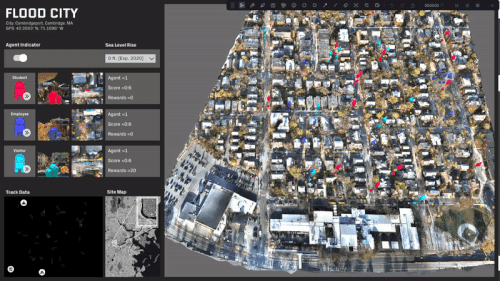
The site is predominantly split with a single access point.
The site is completely split and most destinations are now inaccessible.
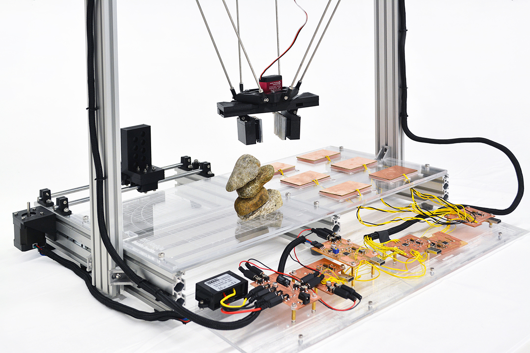
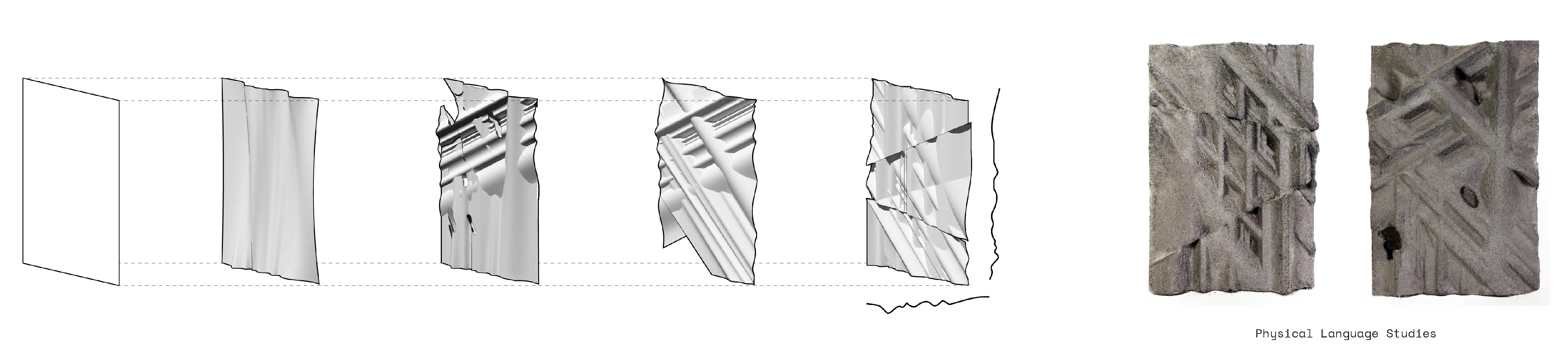
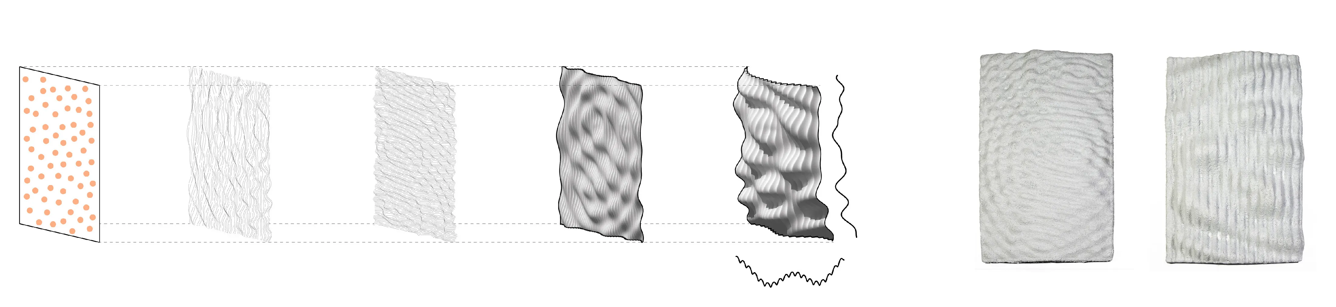
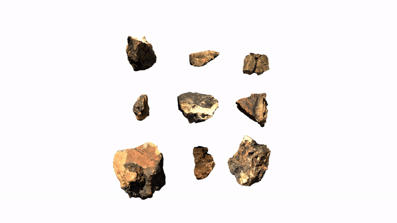
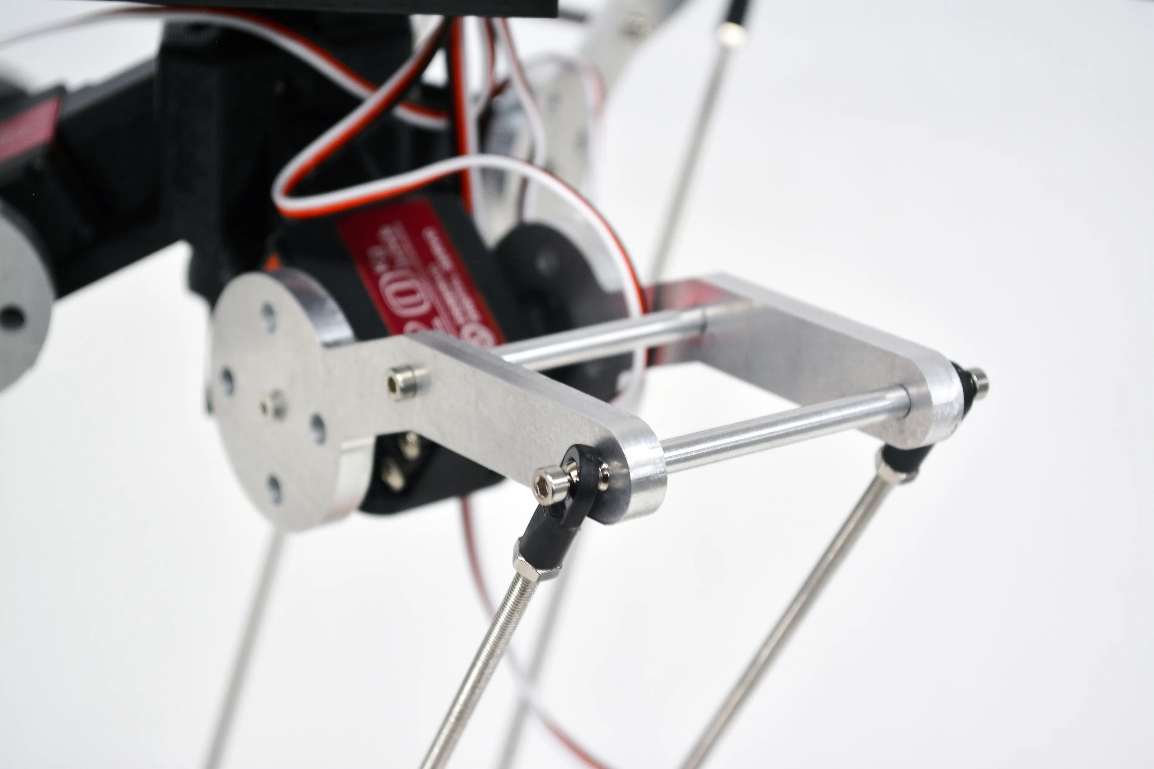
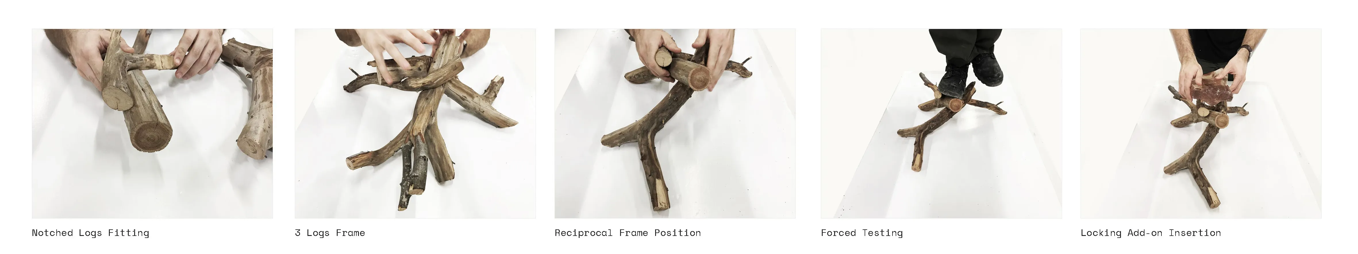
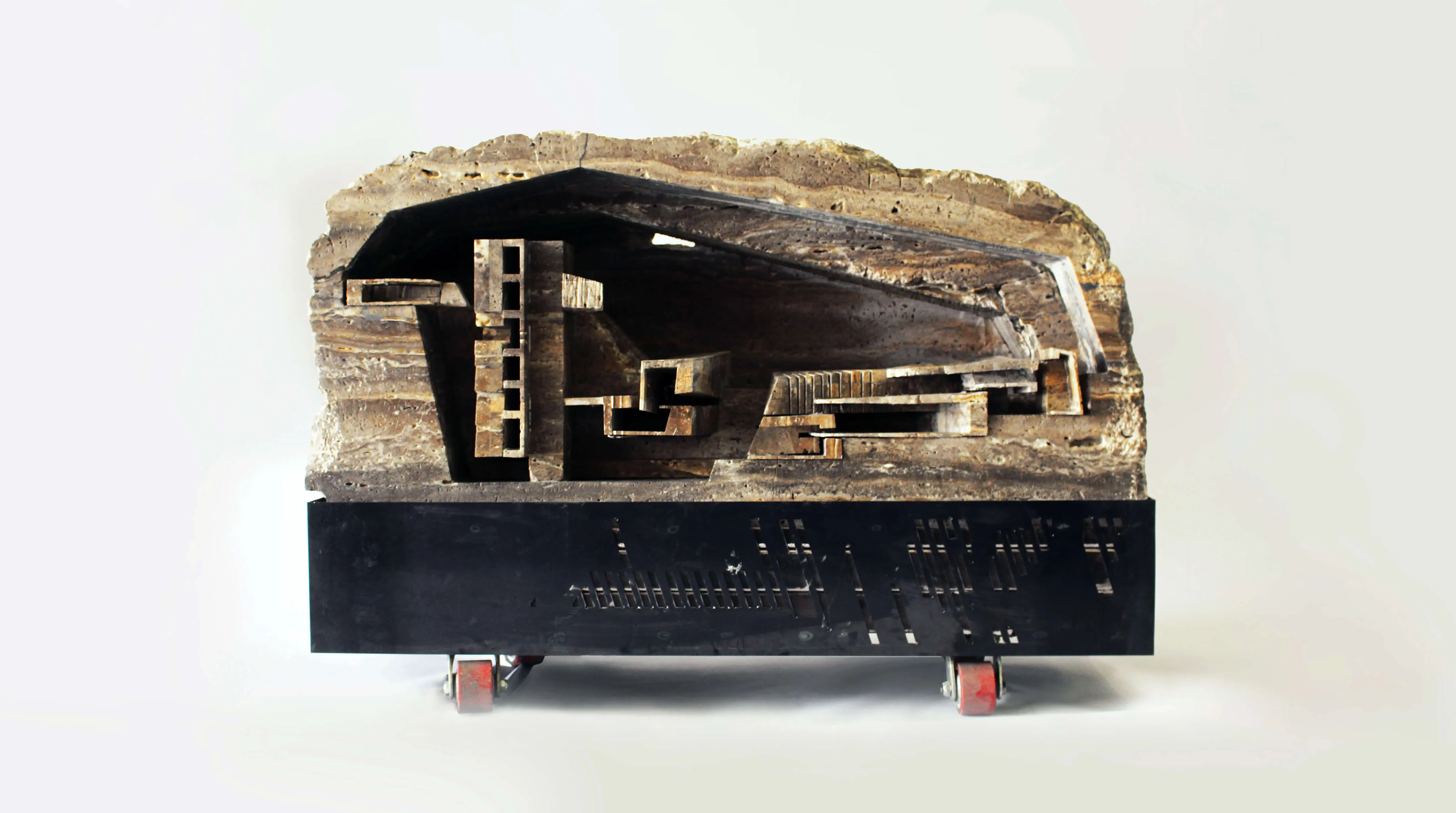
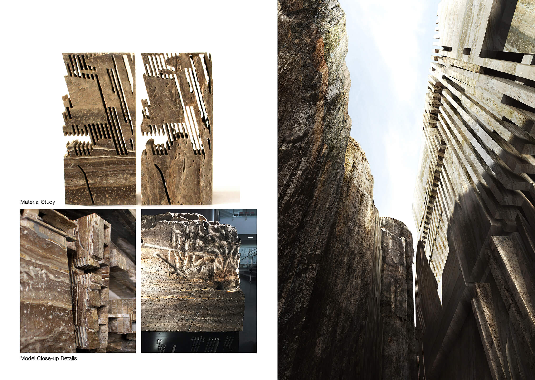
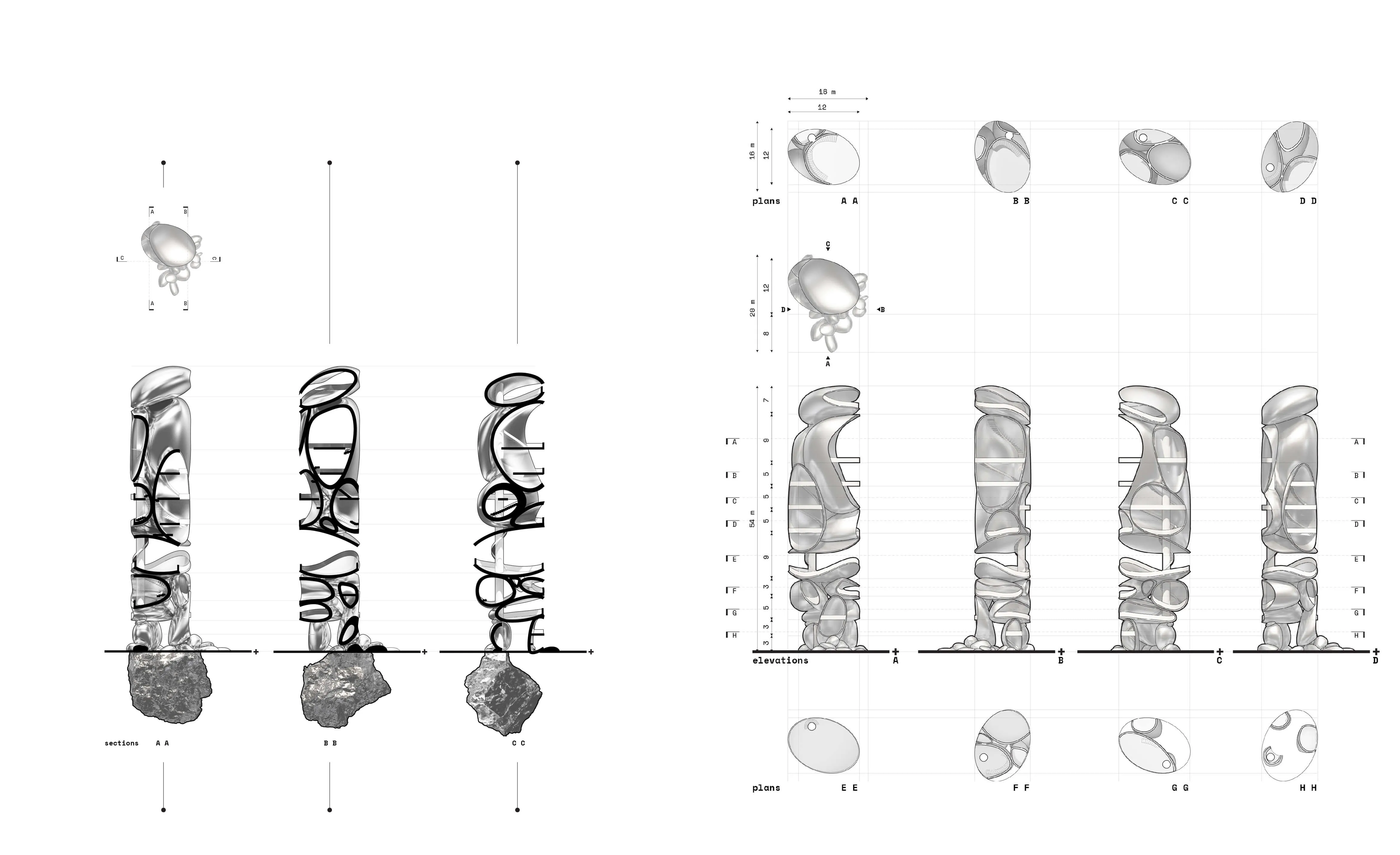
The project begins by looking closely at irregular forms. How can useful information be extracted and utilized in a robotic system. The initial step is to 3D scan rocks and compute their surface deformation, slope of the faces, and how computational workflows could estimate their forms.

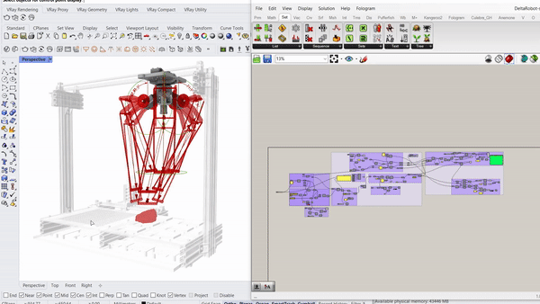
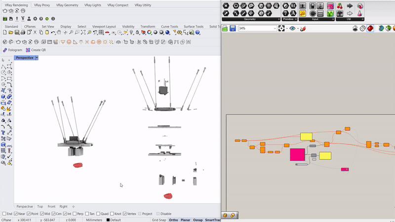
Parametric simulation of the delta robot enabled by the capacitive tracking of the 6 pads allows the model to understand the three key positions the delta arms are going to tween with bounding limits of the servo motors.
Running simulations to orient the rocks along an axis that will enable a smoother and more efficient contact with the gripper.
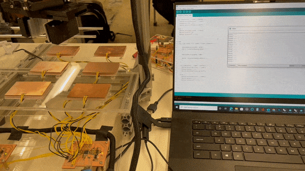
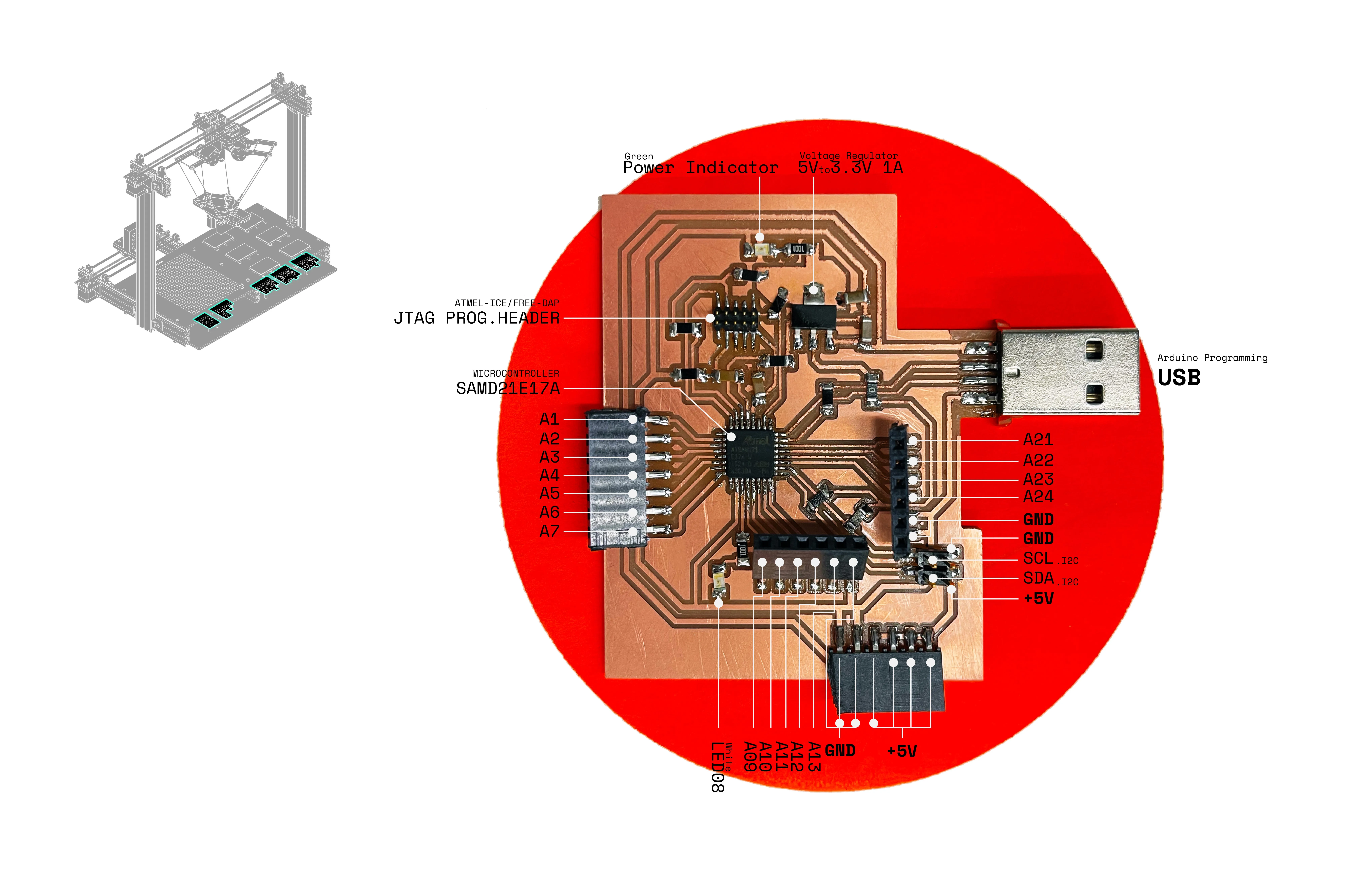
Capacitive sensors are used as the pickup detection system, where once a rock is placed on one of the 6 pads, the information is relayed to the processor to initiate a pickup command to the que.
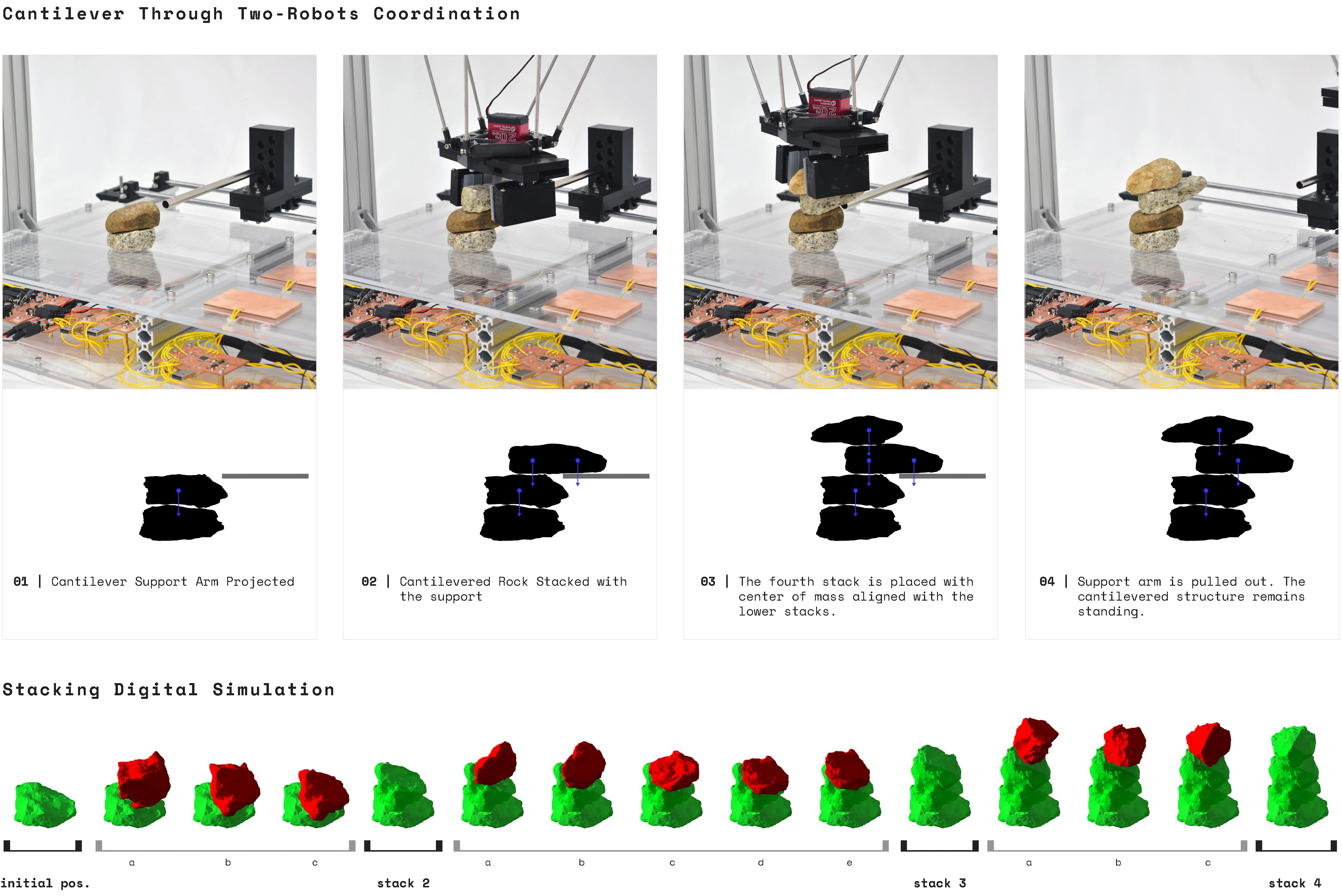
The arm projects forward to act as a support based or scaffolding for the rock above. This arm is gently pulled out after the rock ontop is stabilized by another rock on top of it.
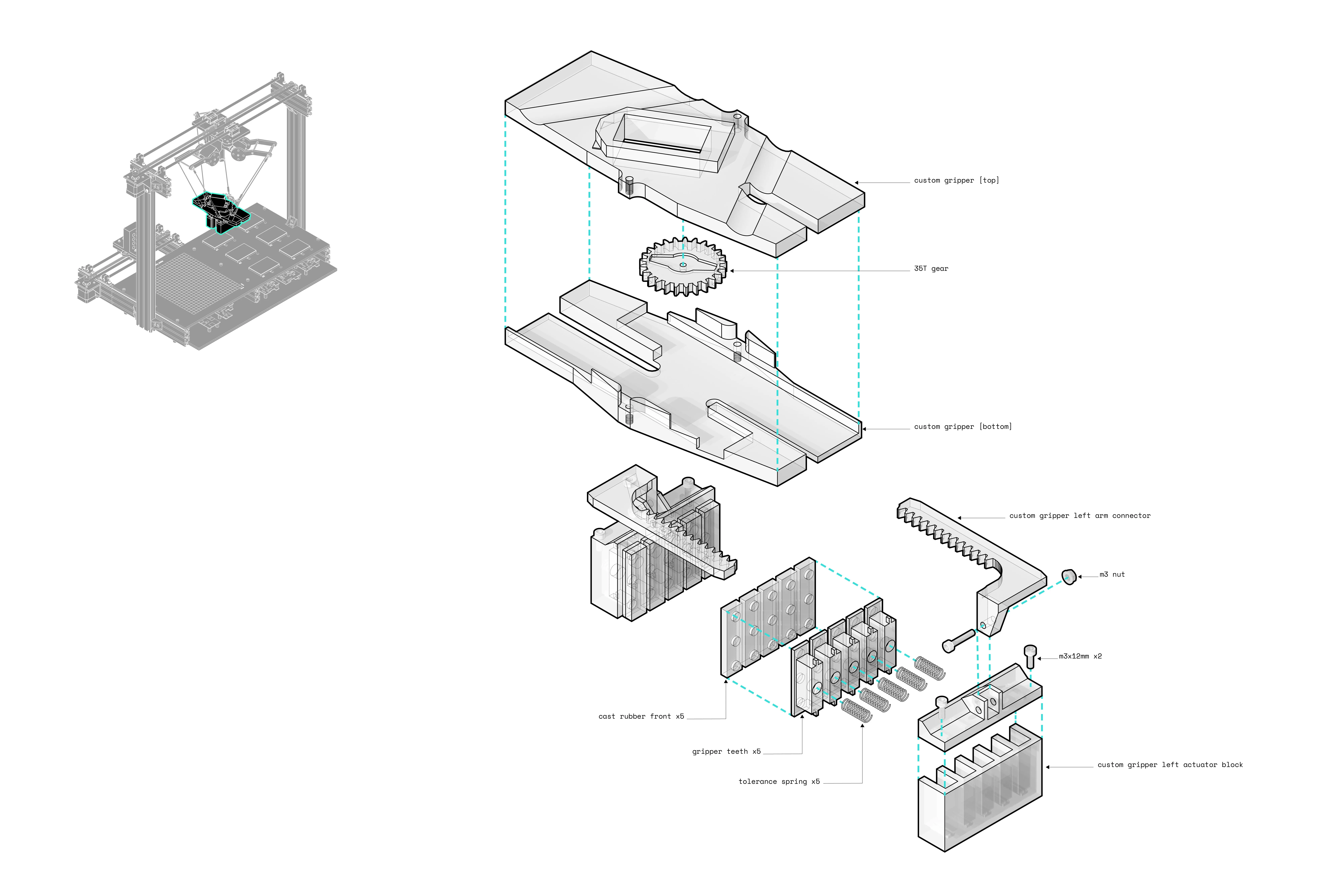
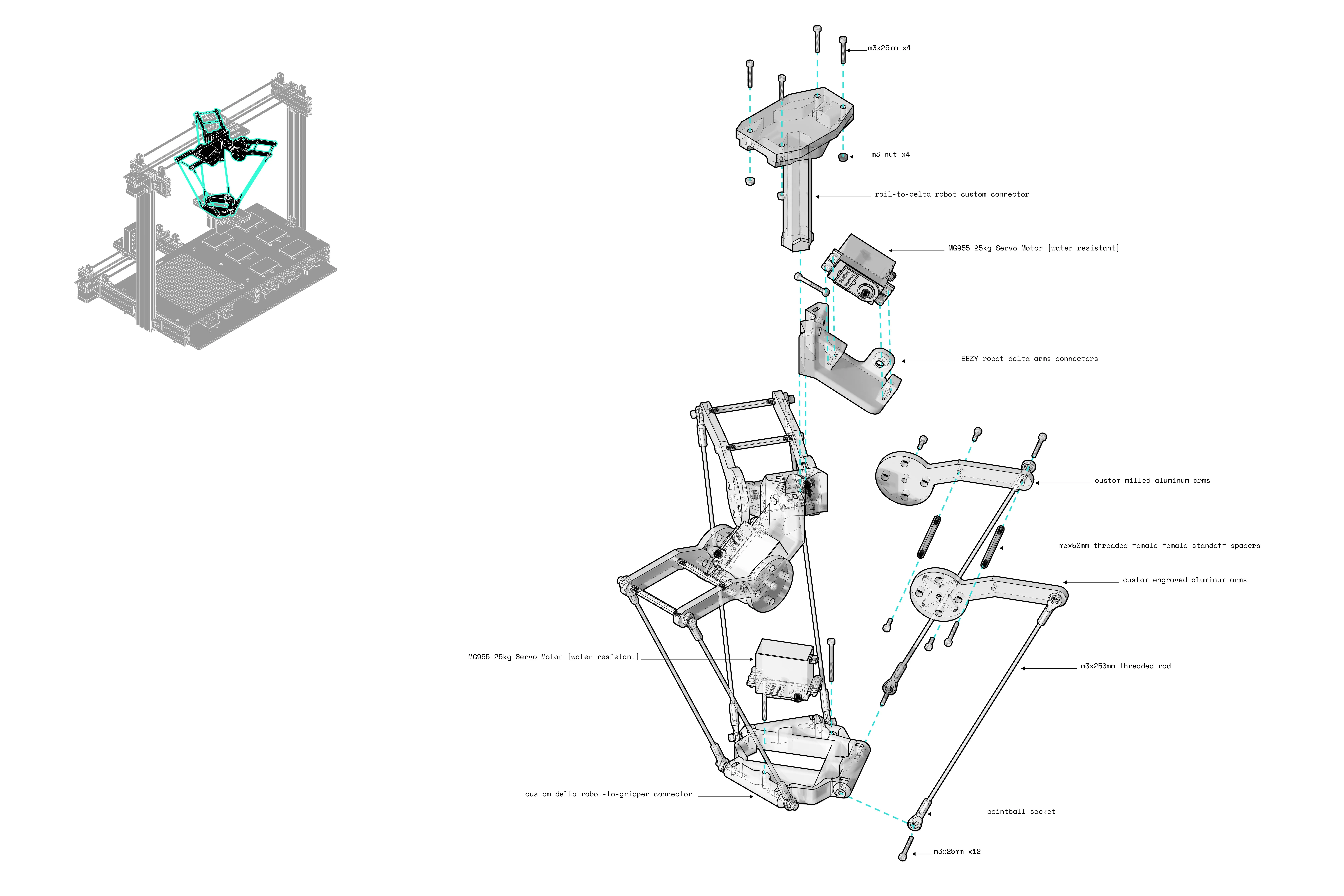
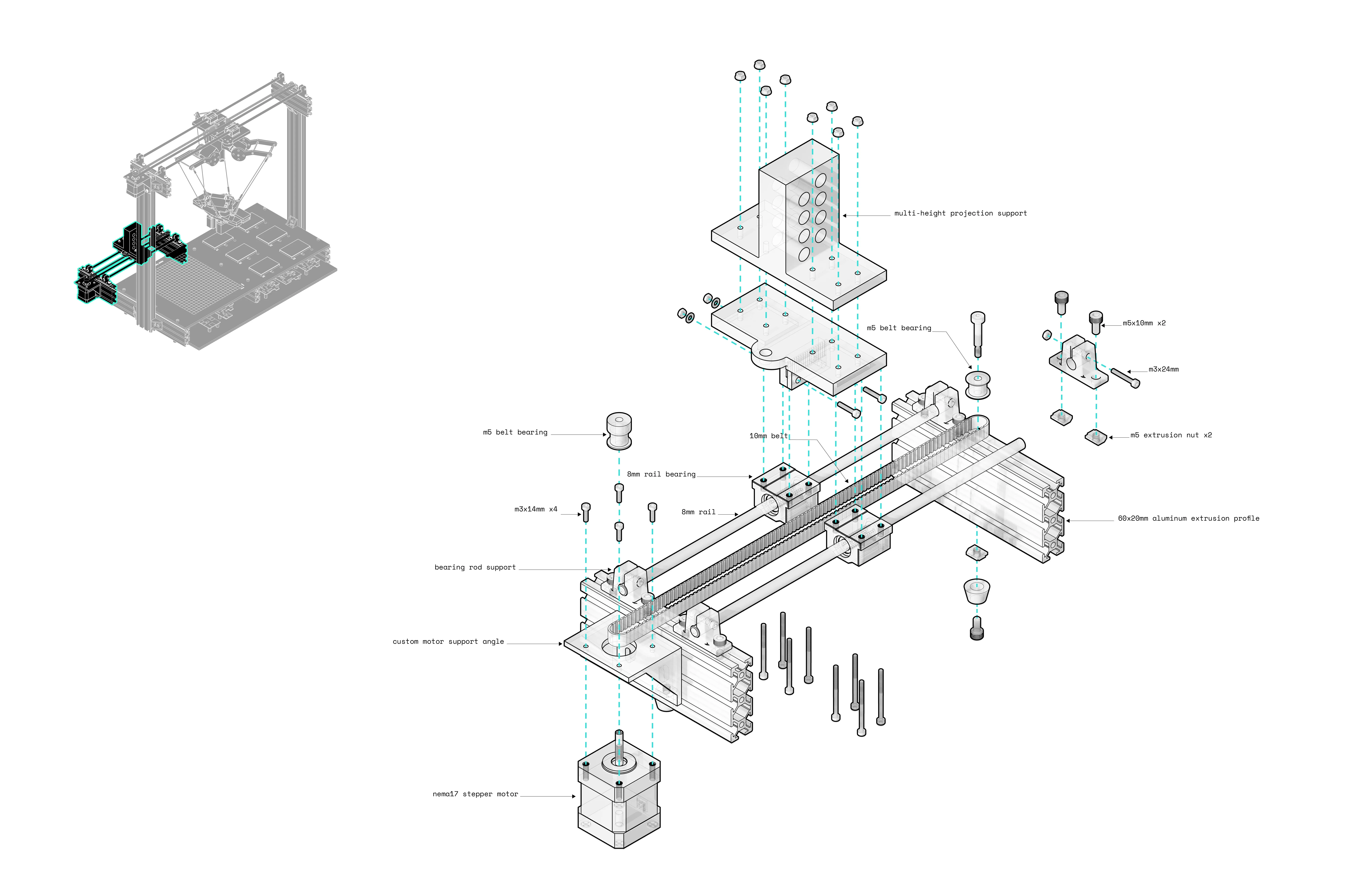
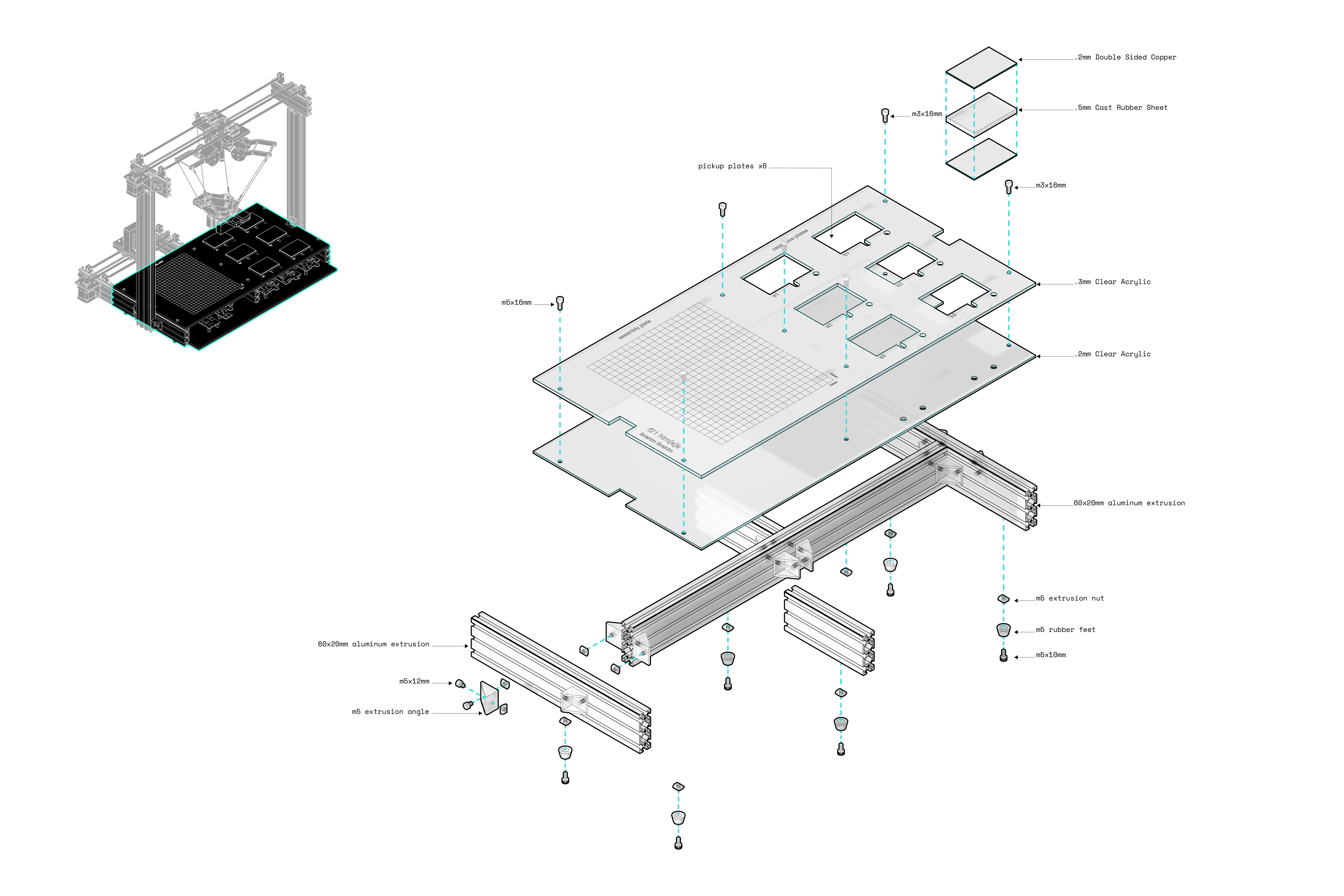
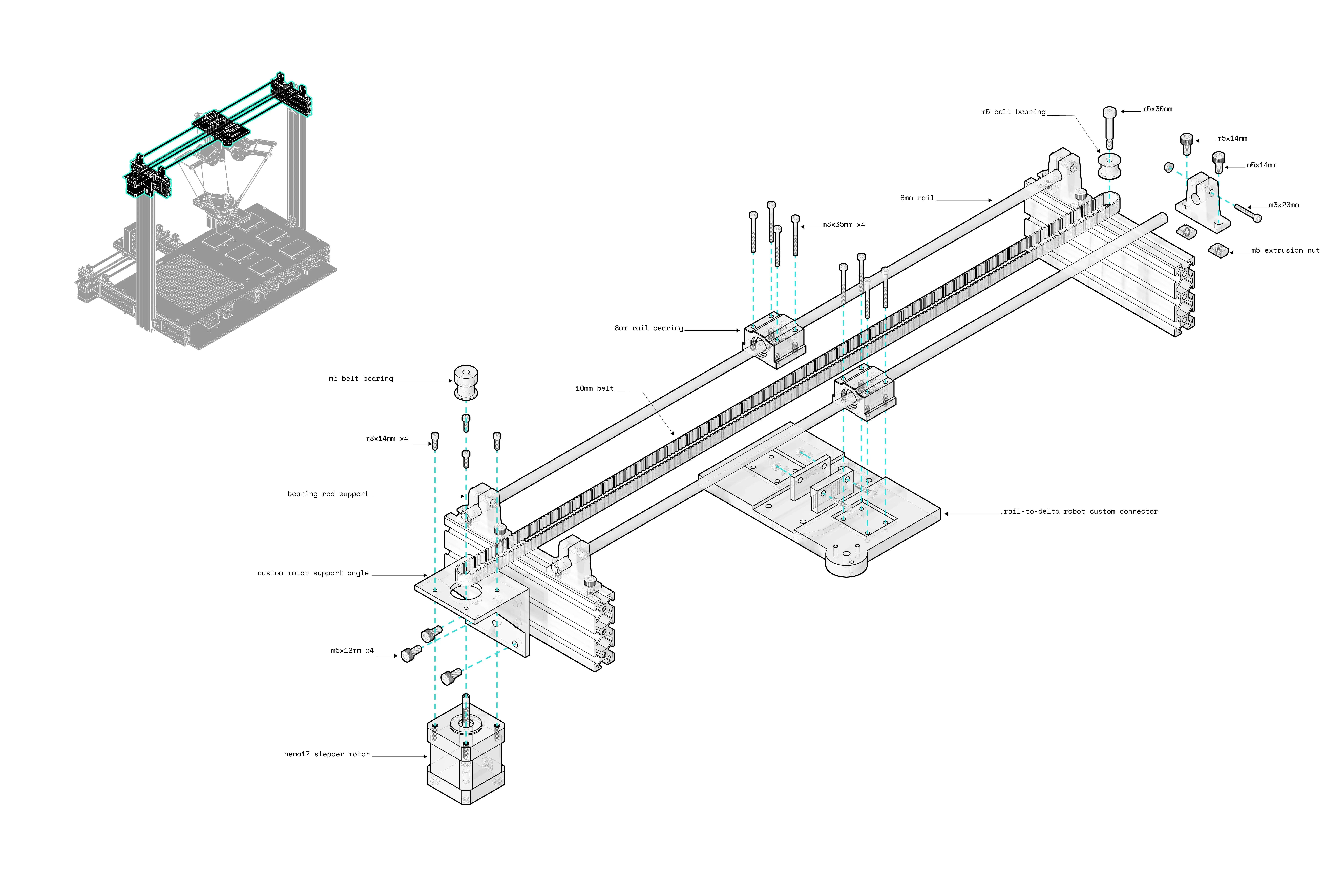
The machine is composed of several systems working together to construct novel and precise compositions.
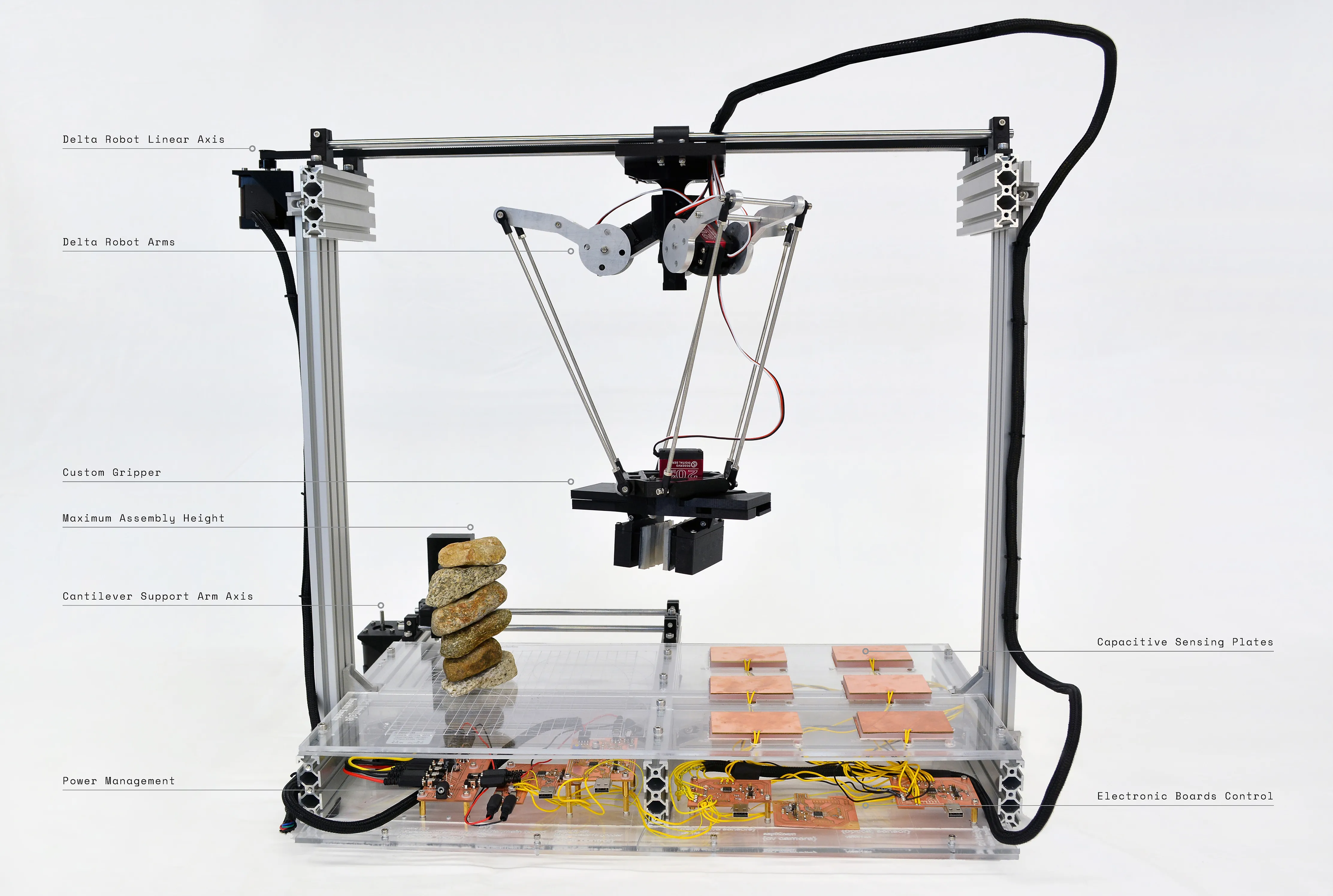
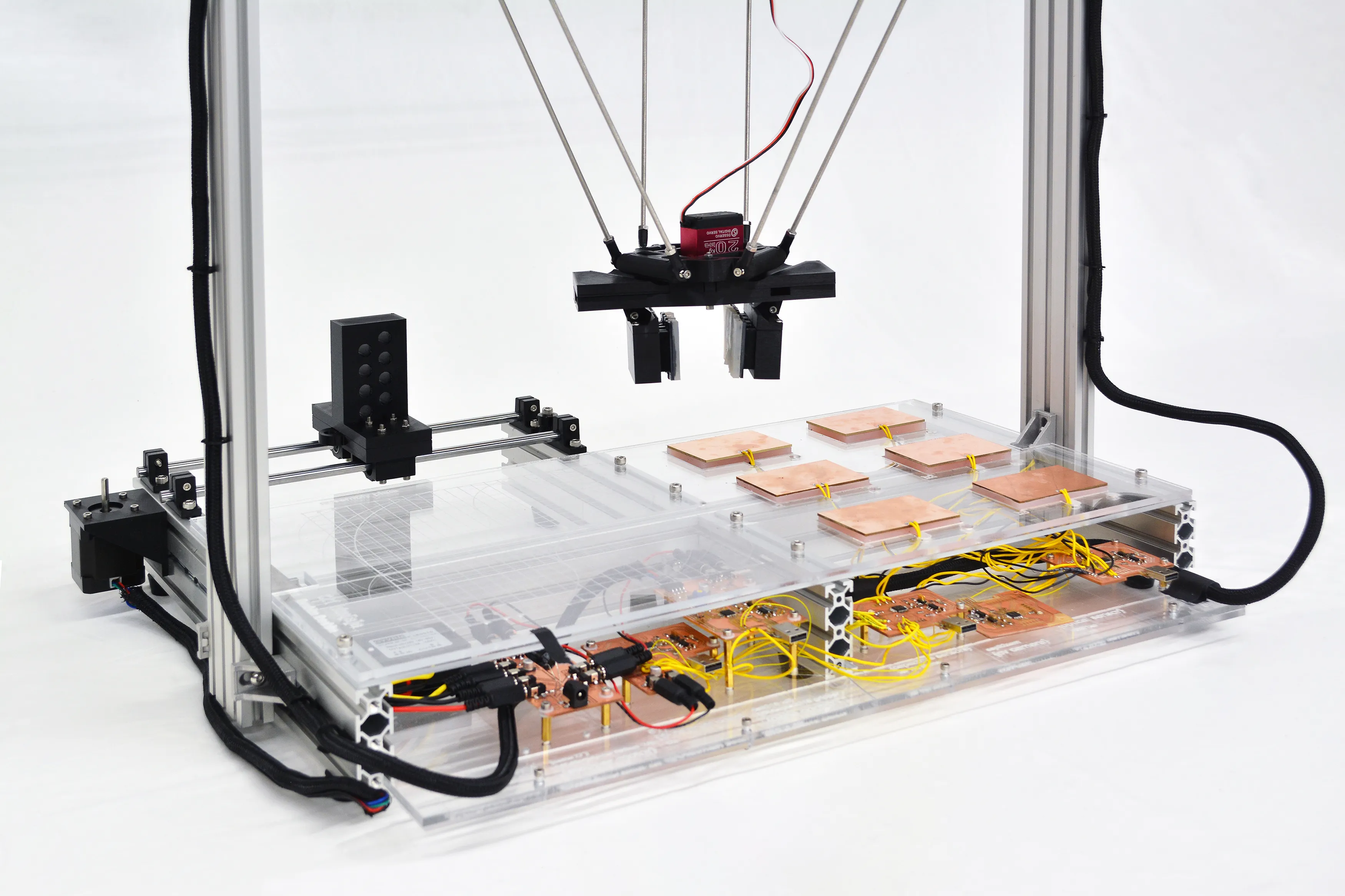
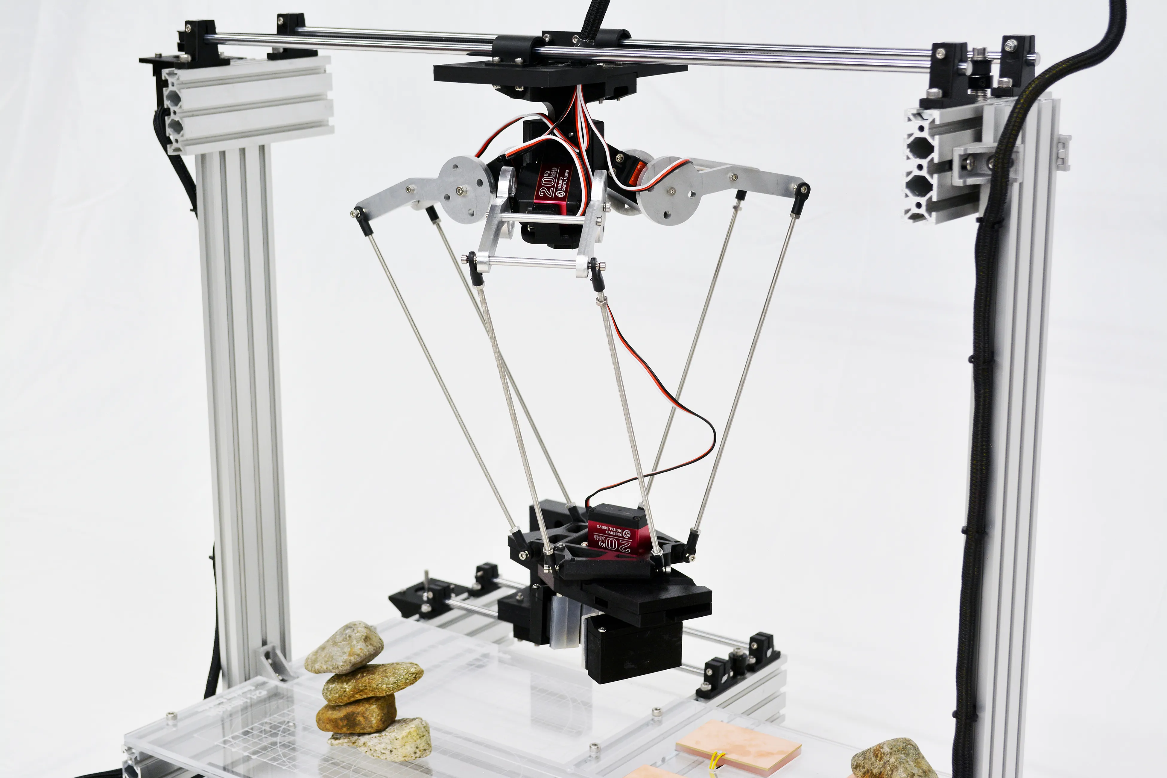
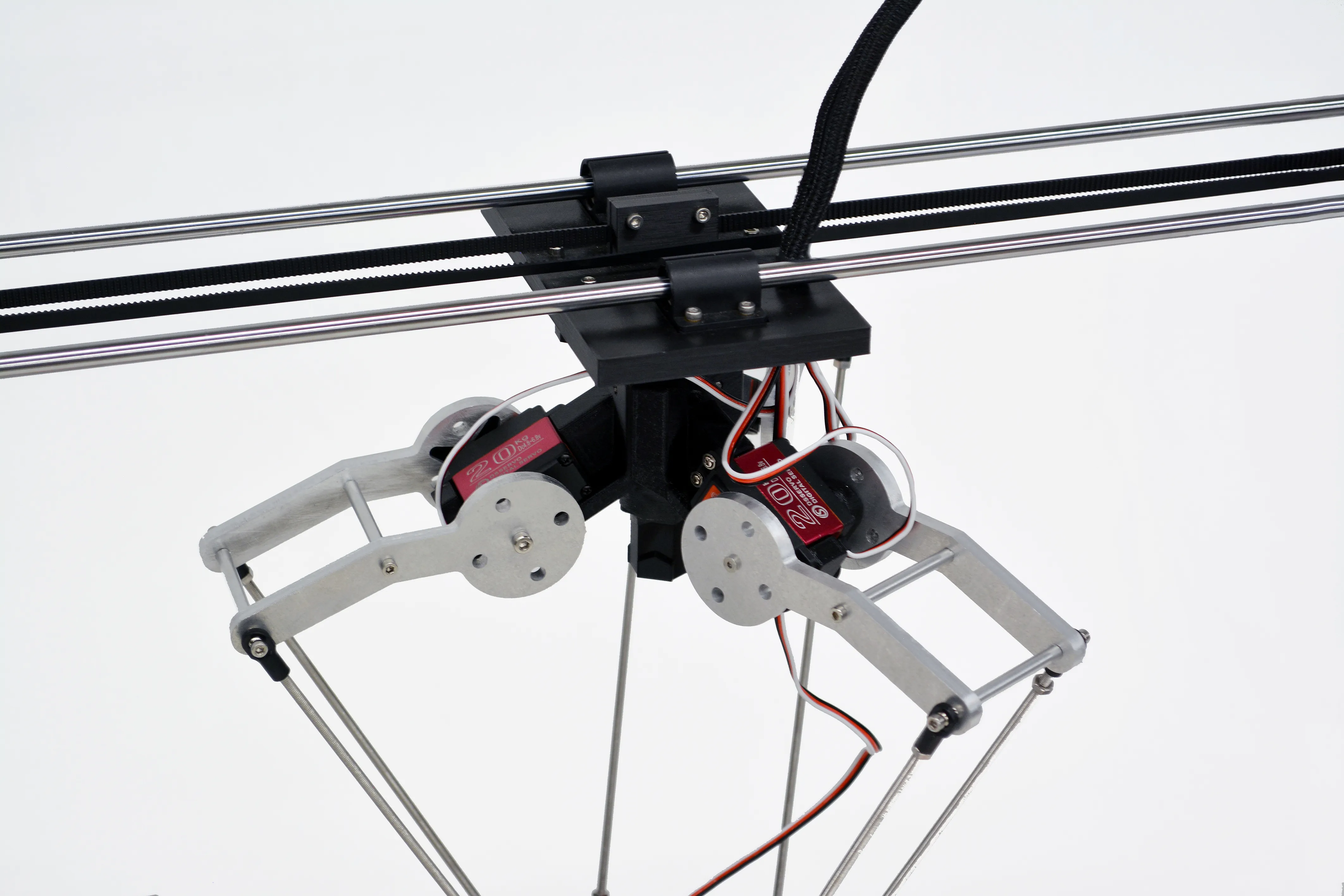
A technical inside look into the components of each system.
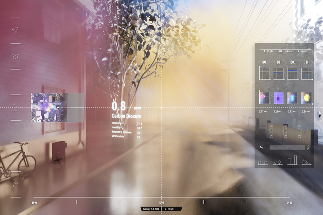
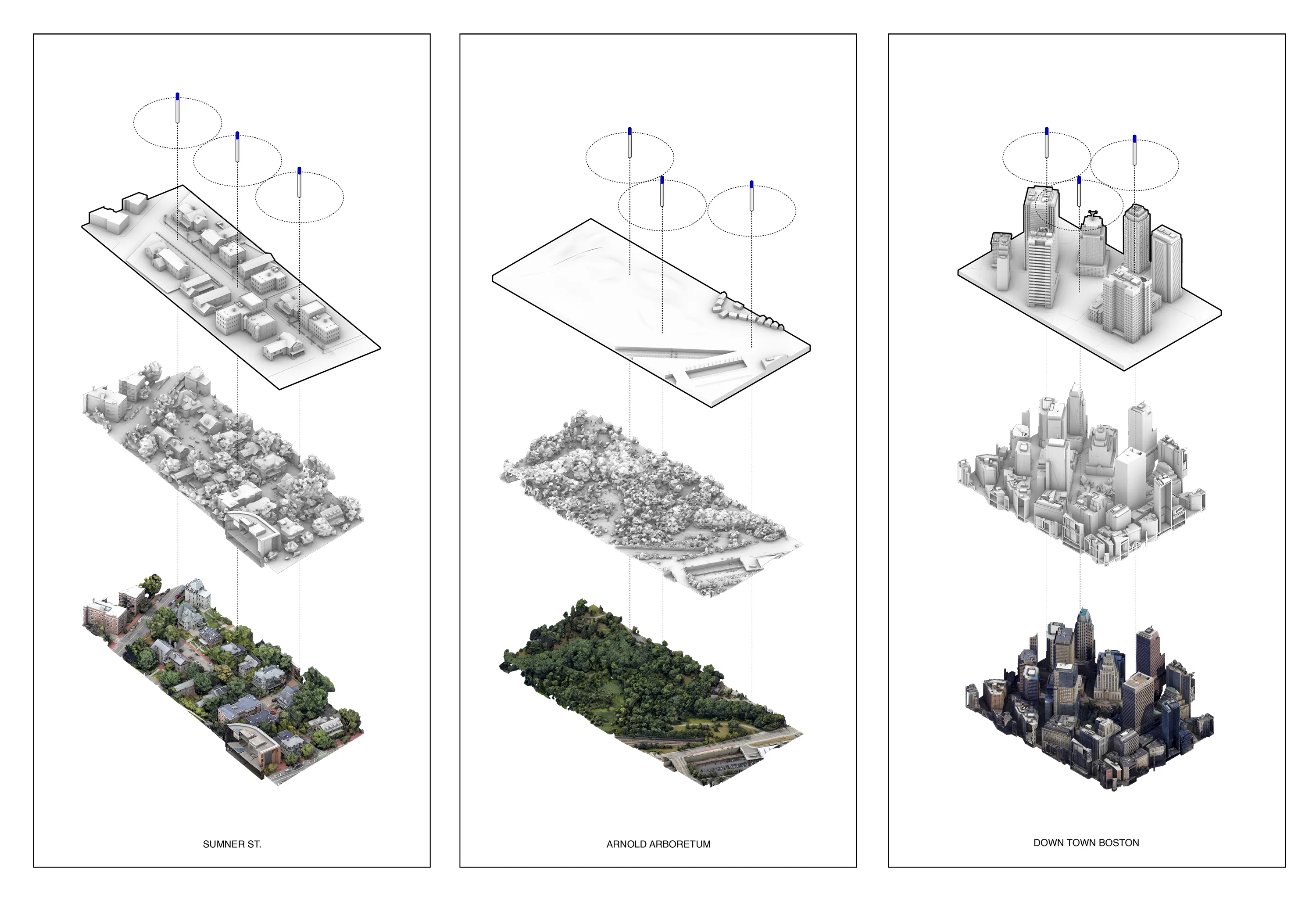
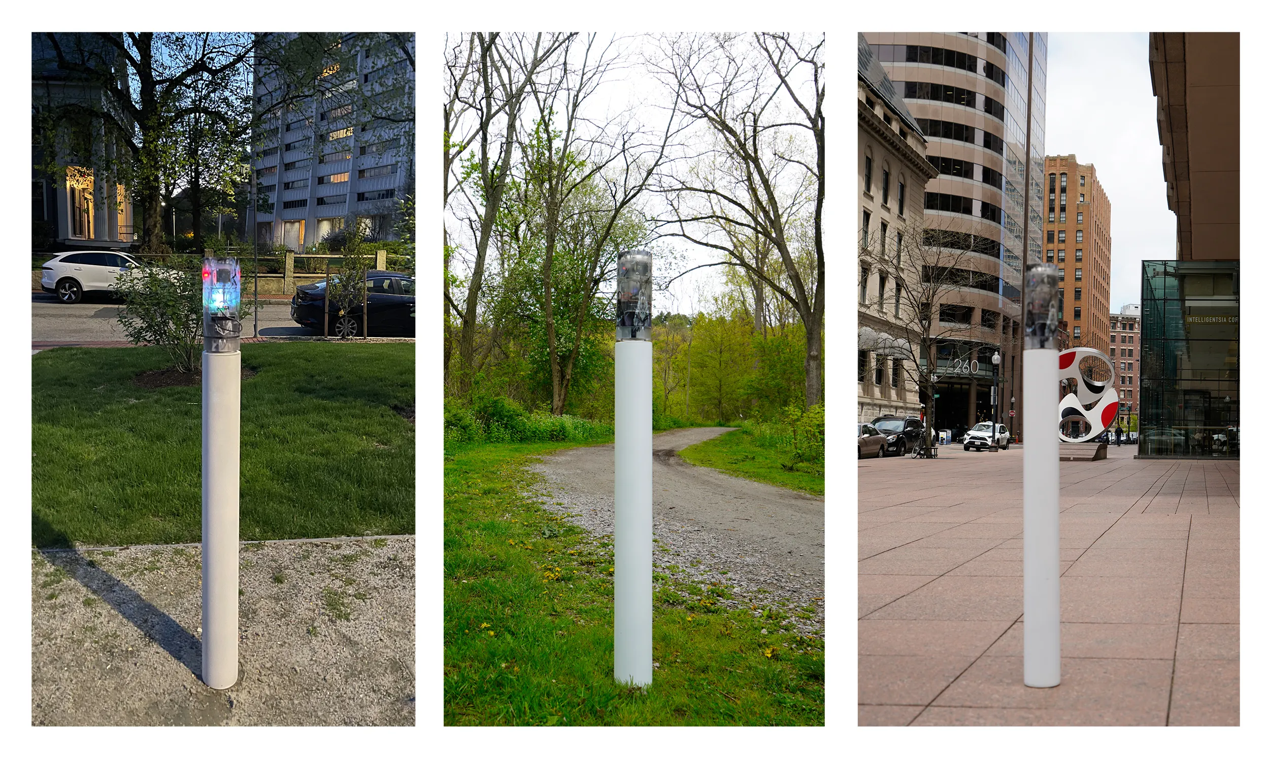
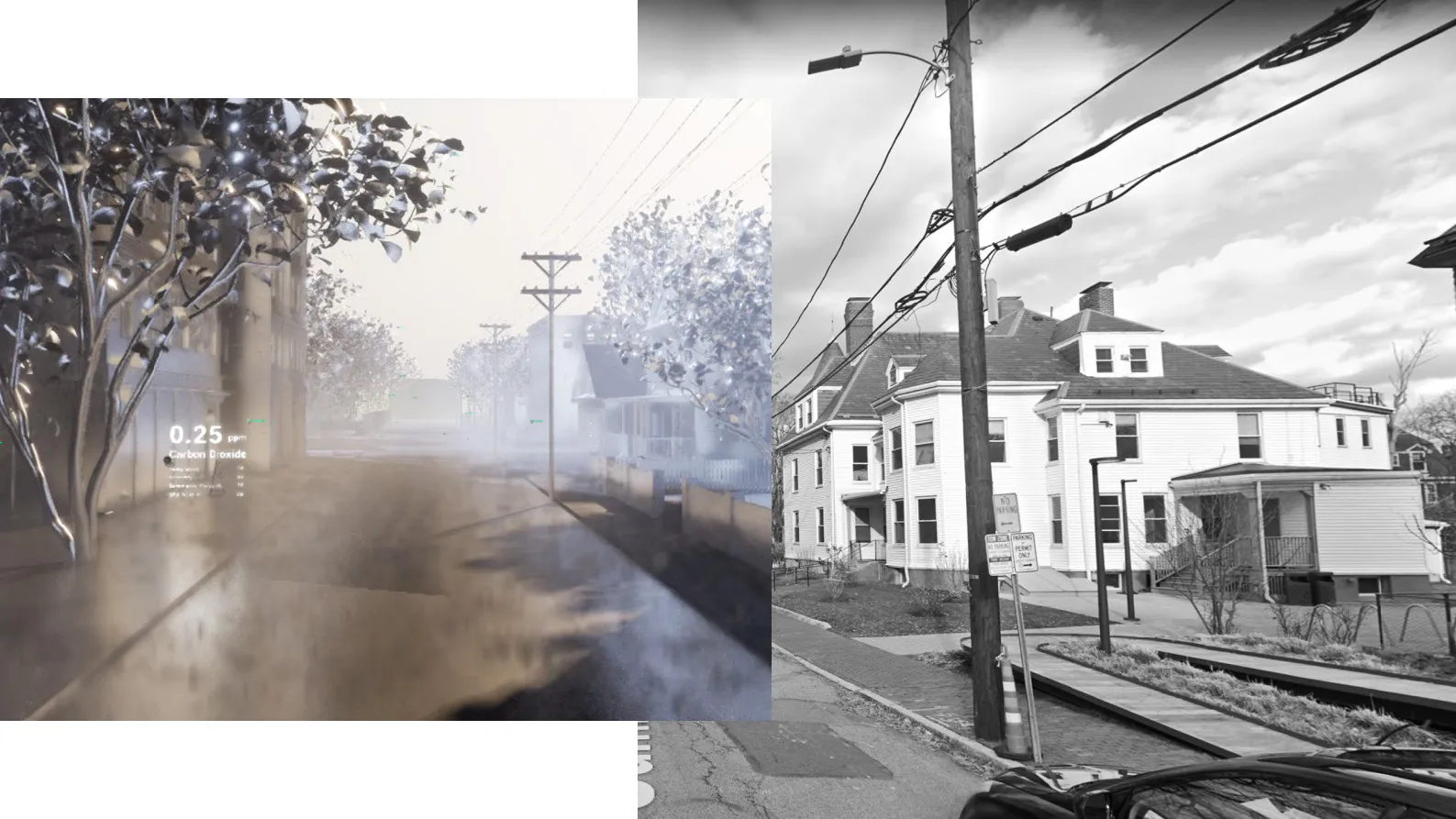
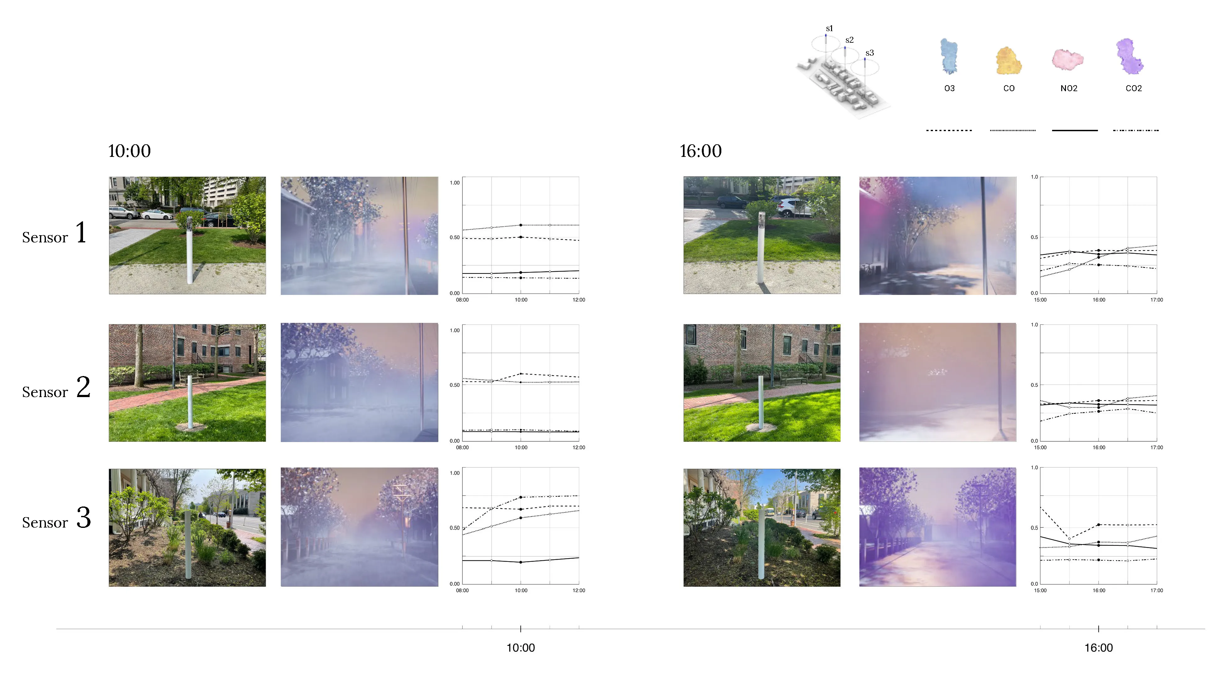
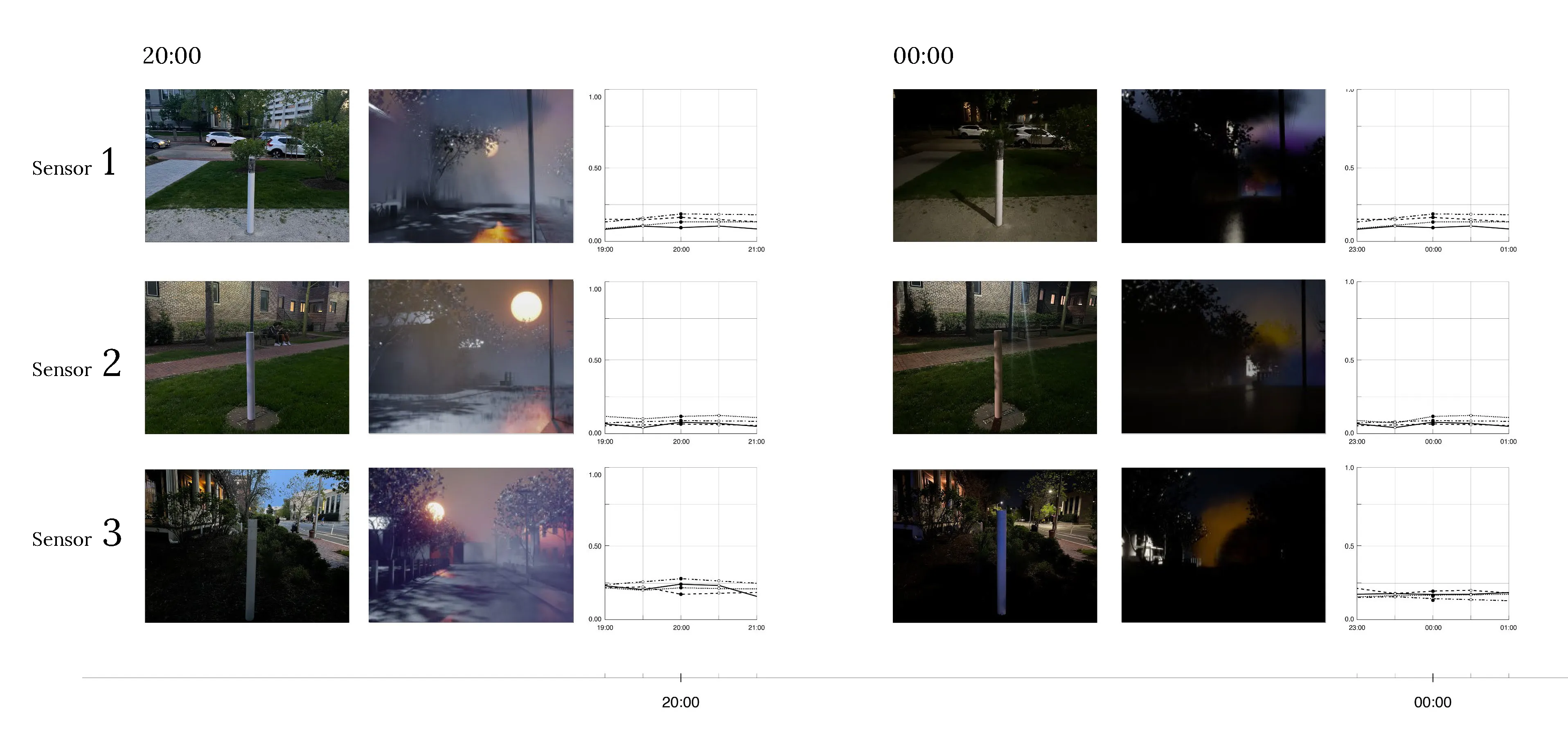
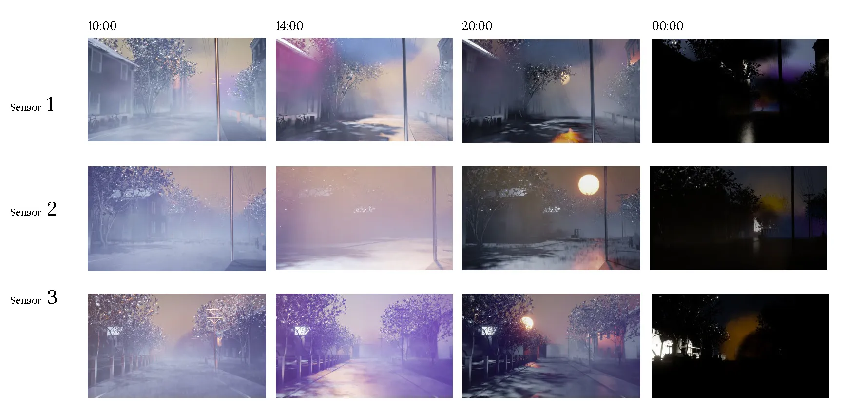
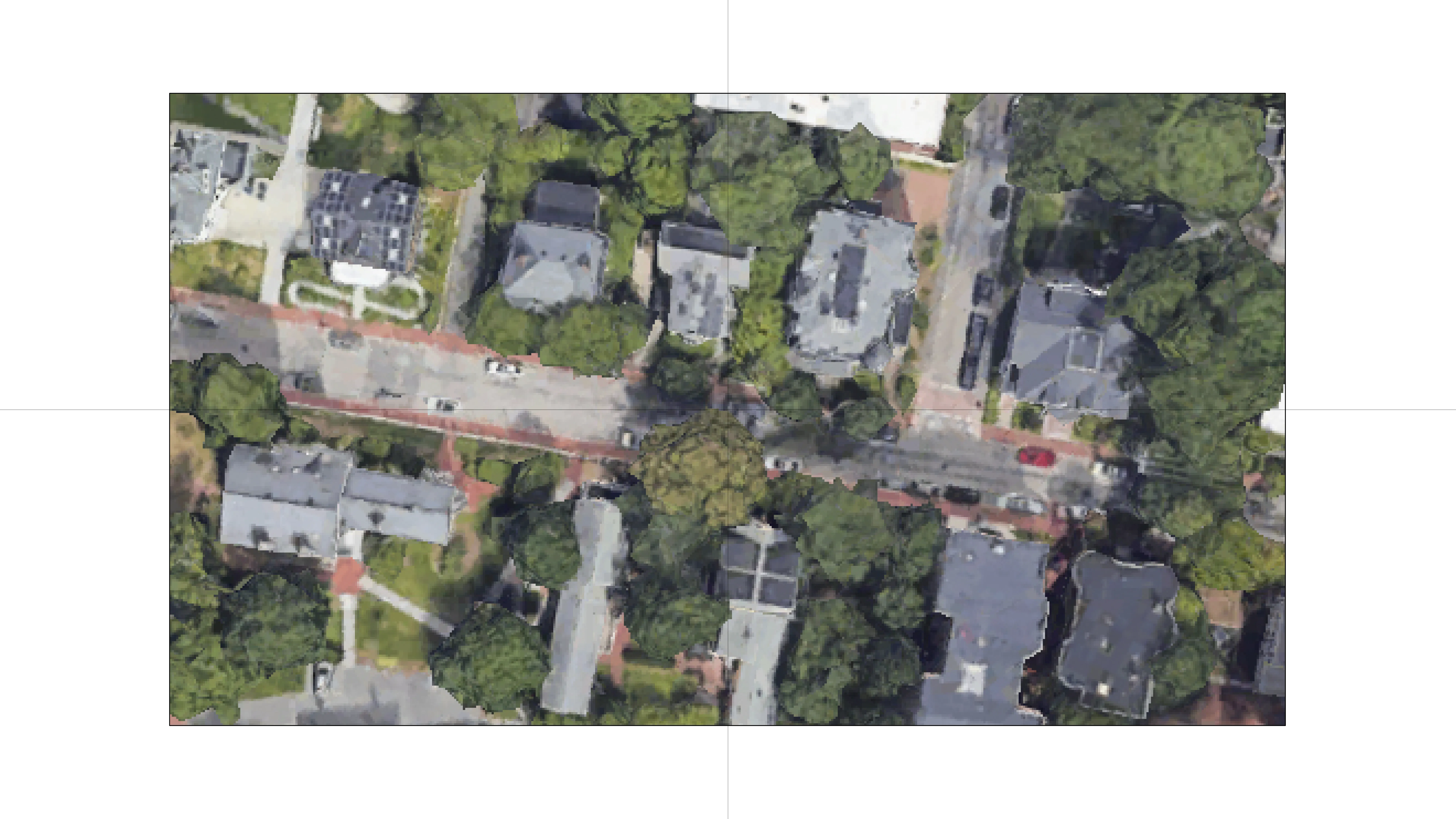
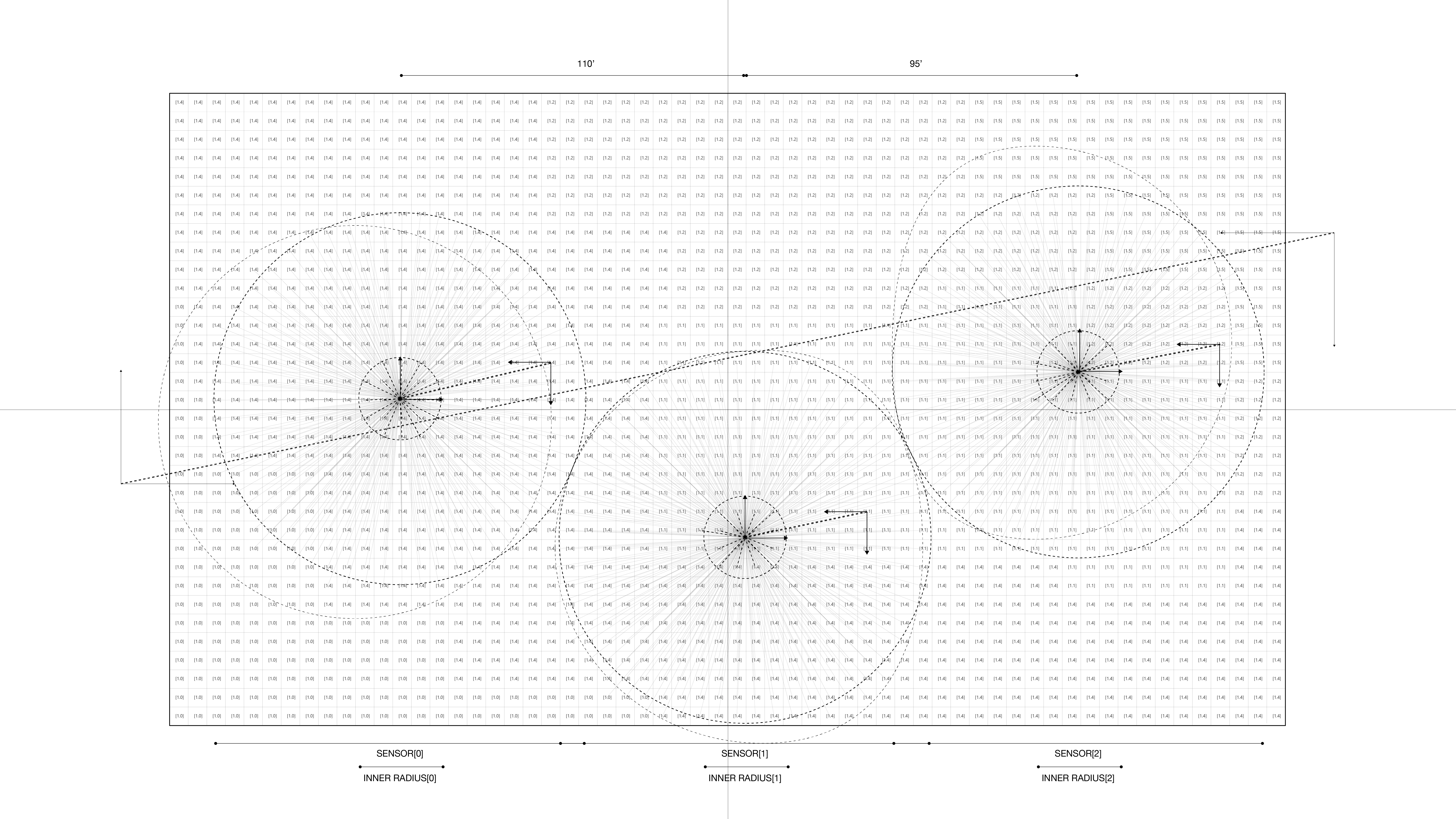
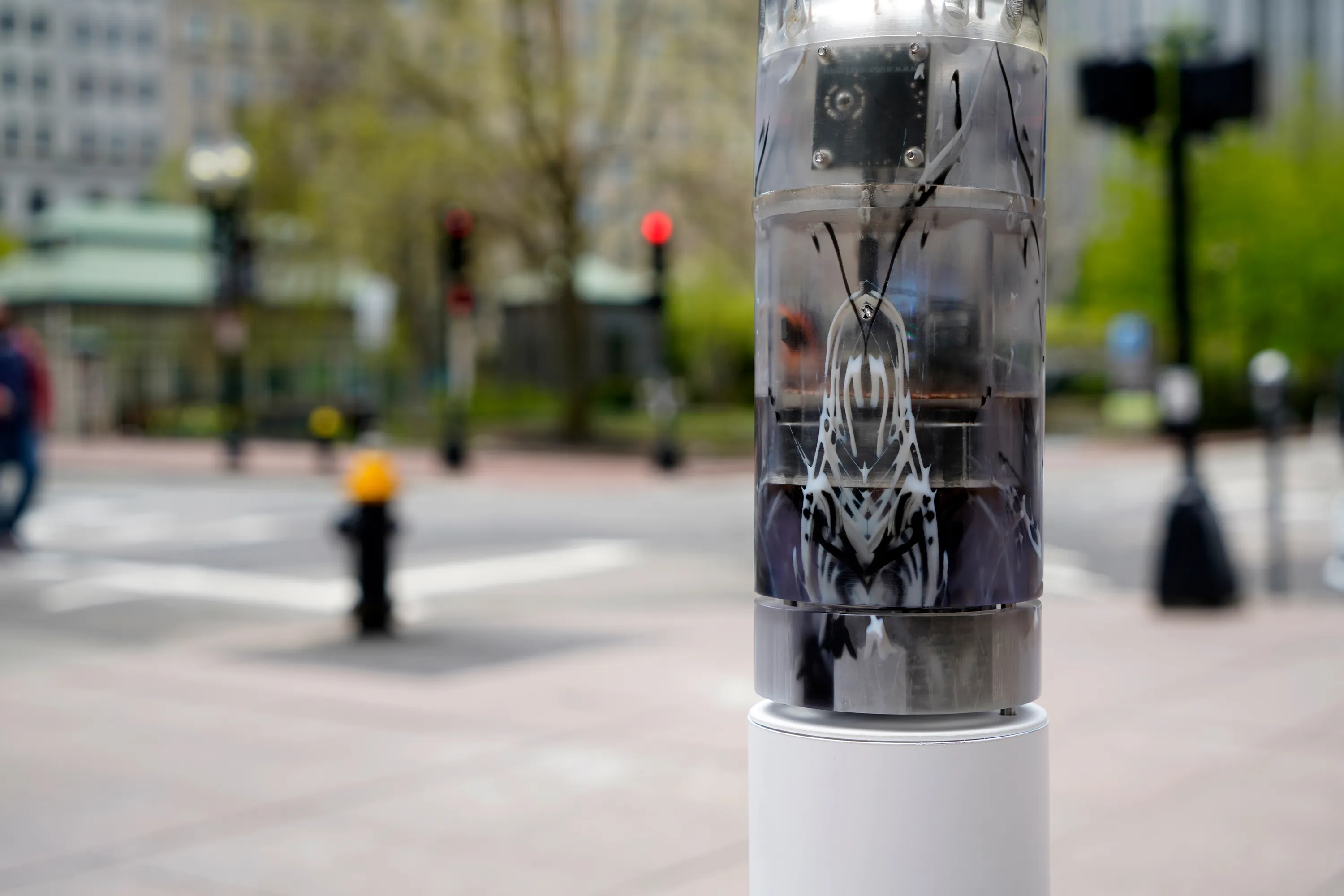
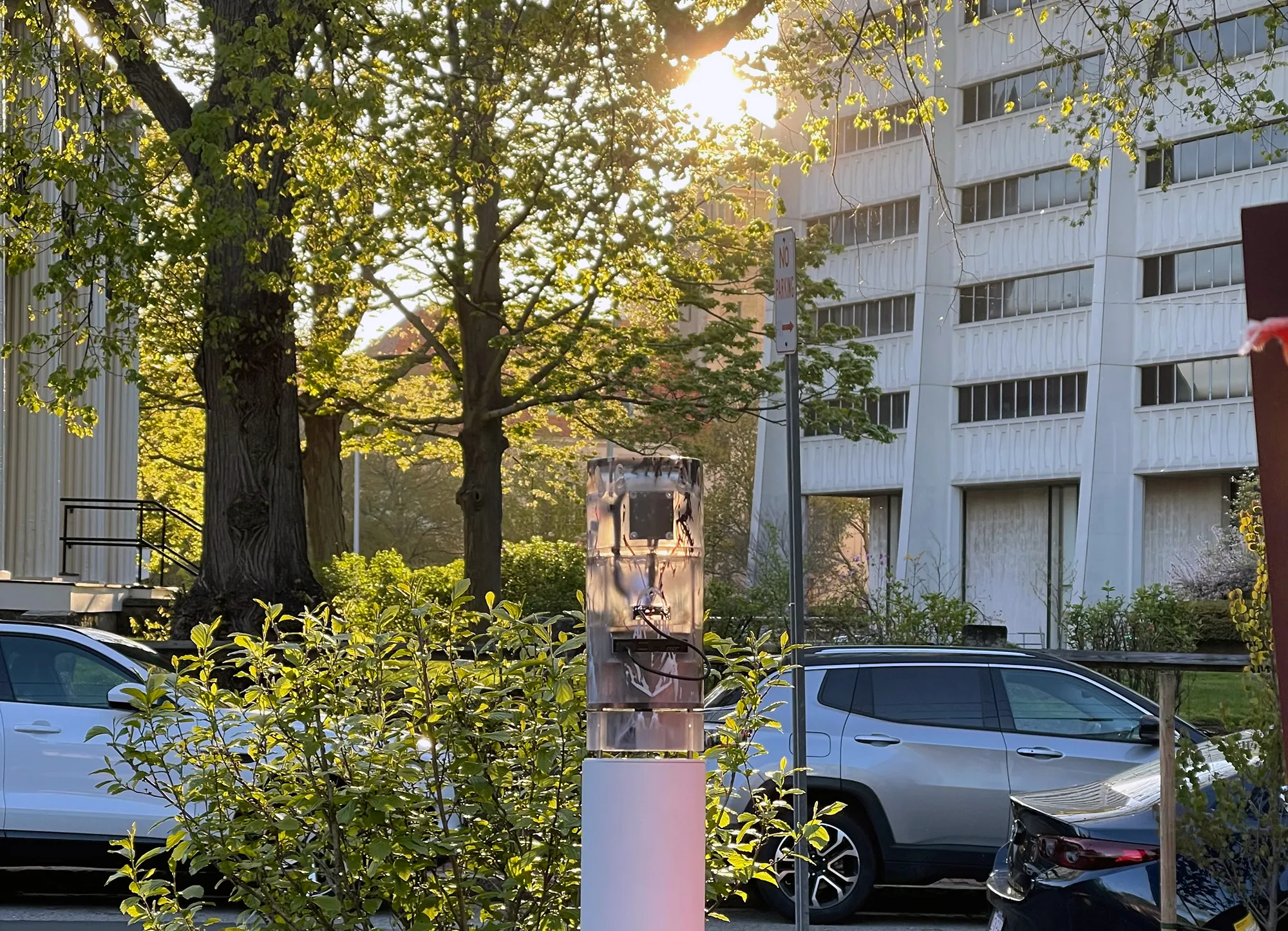
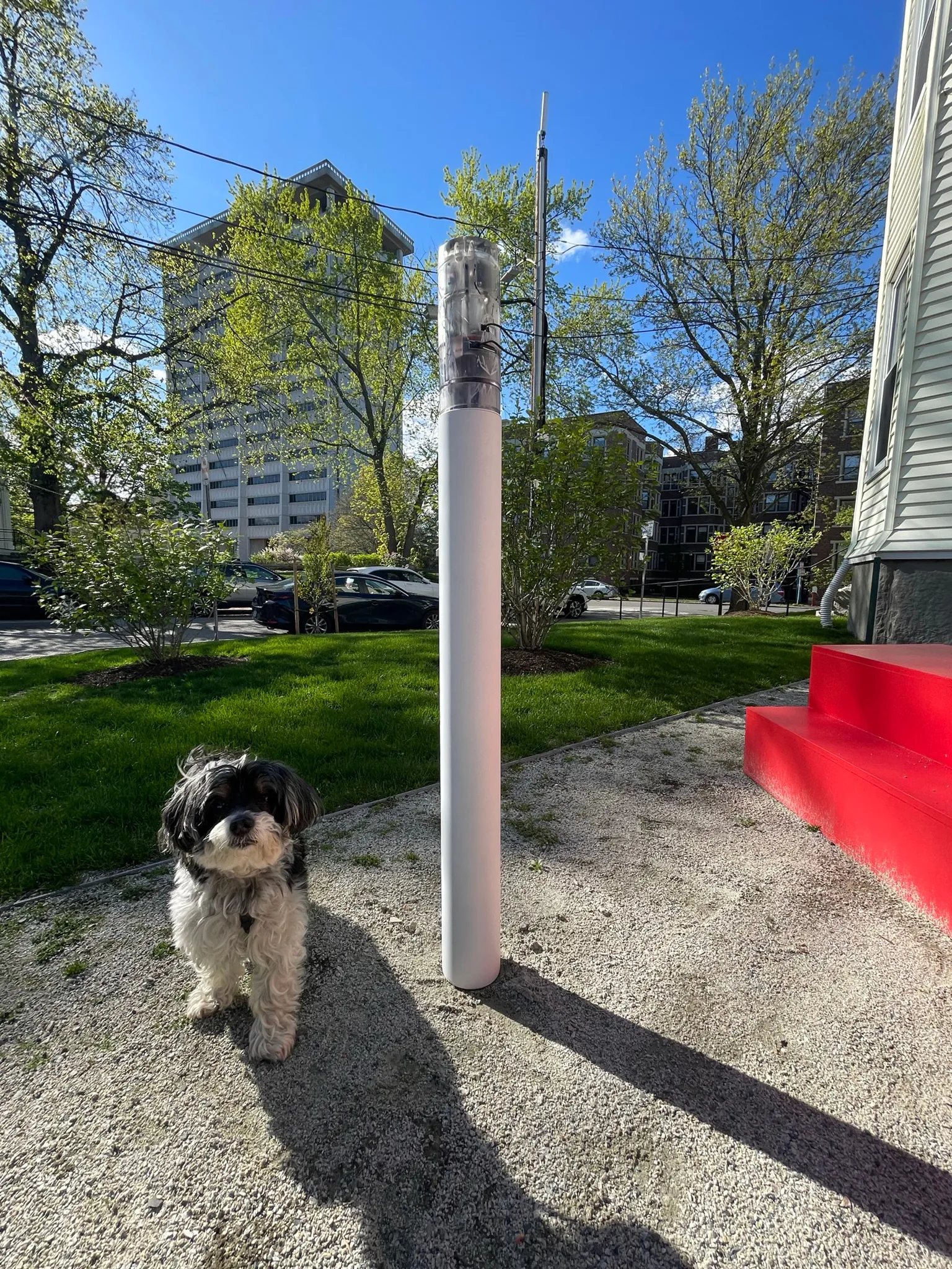
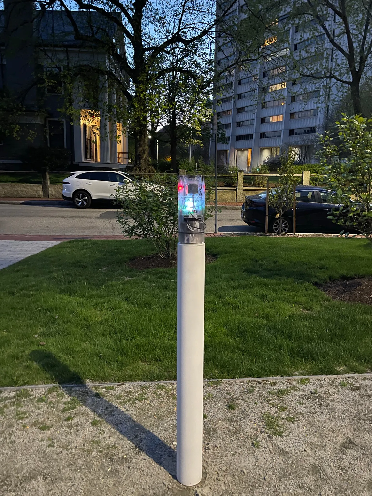
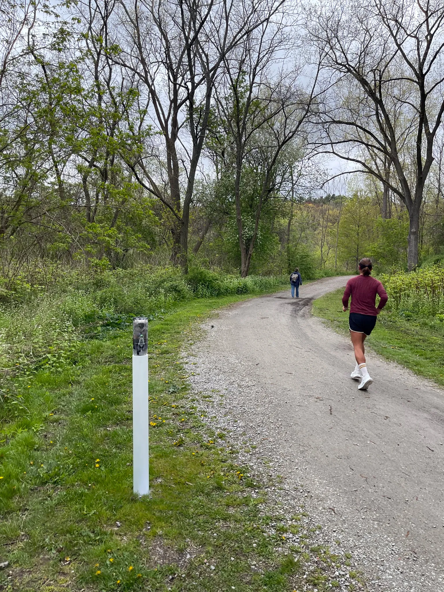
The project was studied in three distinct contexts. First,the primary testing site was in Sumner Street in Cambridge, MA. A small-scale neighborhoodstrip that connects several Harvard University buildings and features a mix ofresidential housing structures and academic centers. The site is situated nearbusy squares and has become an active line of transportation after the area wasconverted into a single-way traffic street. Given its proximity to our baselocation it serves as an ideal testing ground for both the development and theproduct testing phases. The assumption for this site choice is to understandhow air quality is affected by various times of the day, which dictate traffic inand out of academic and office spaces in the area.
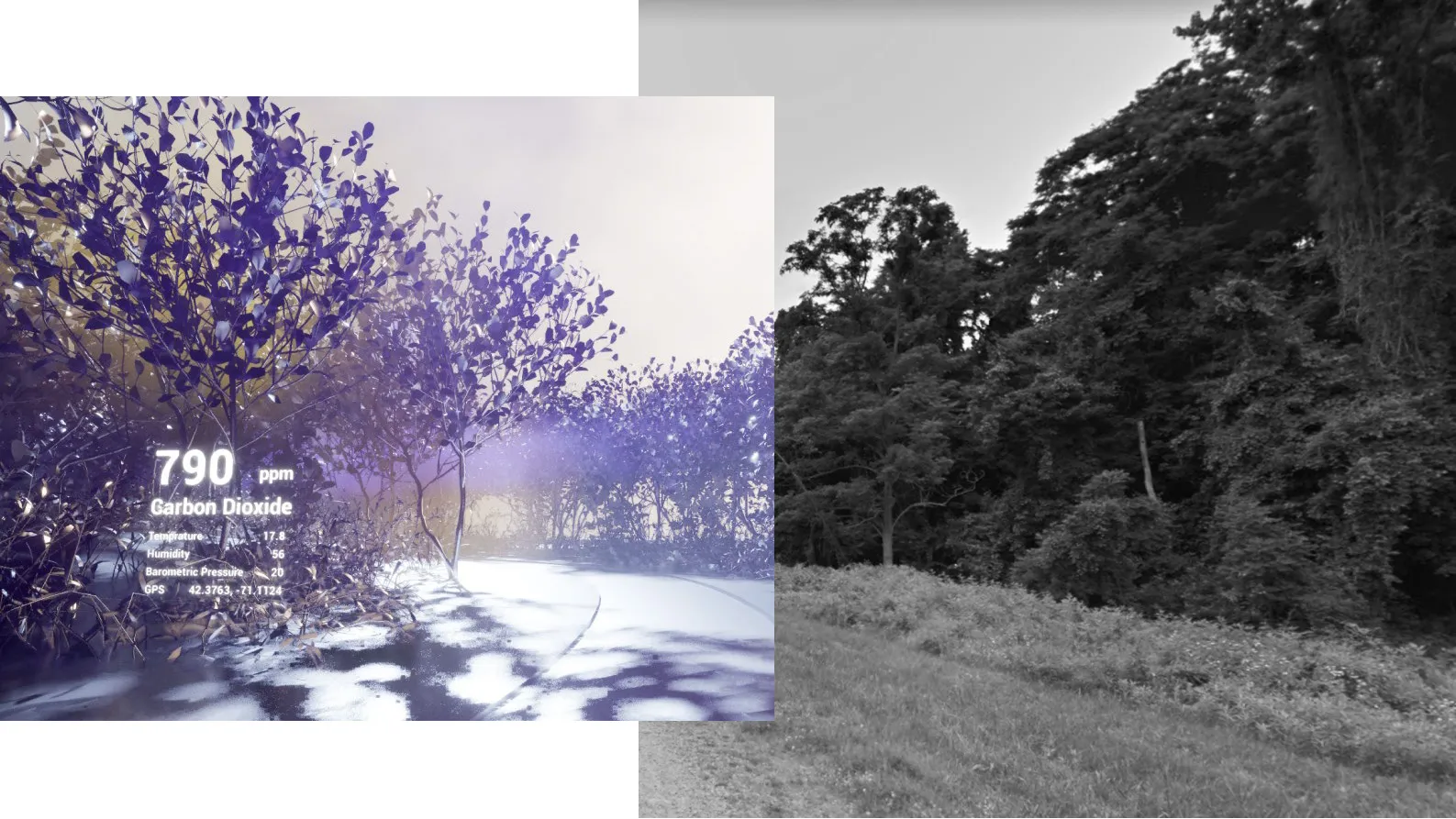
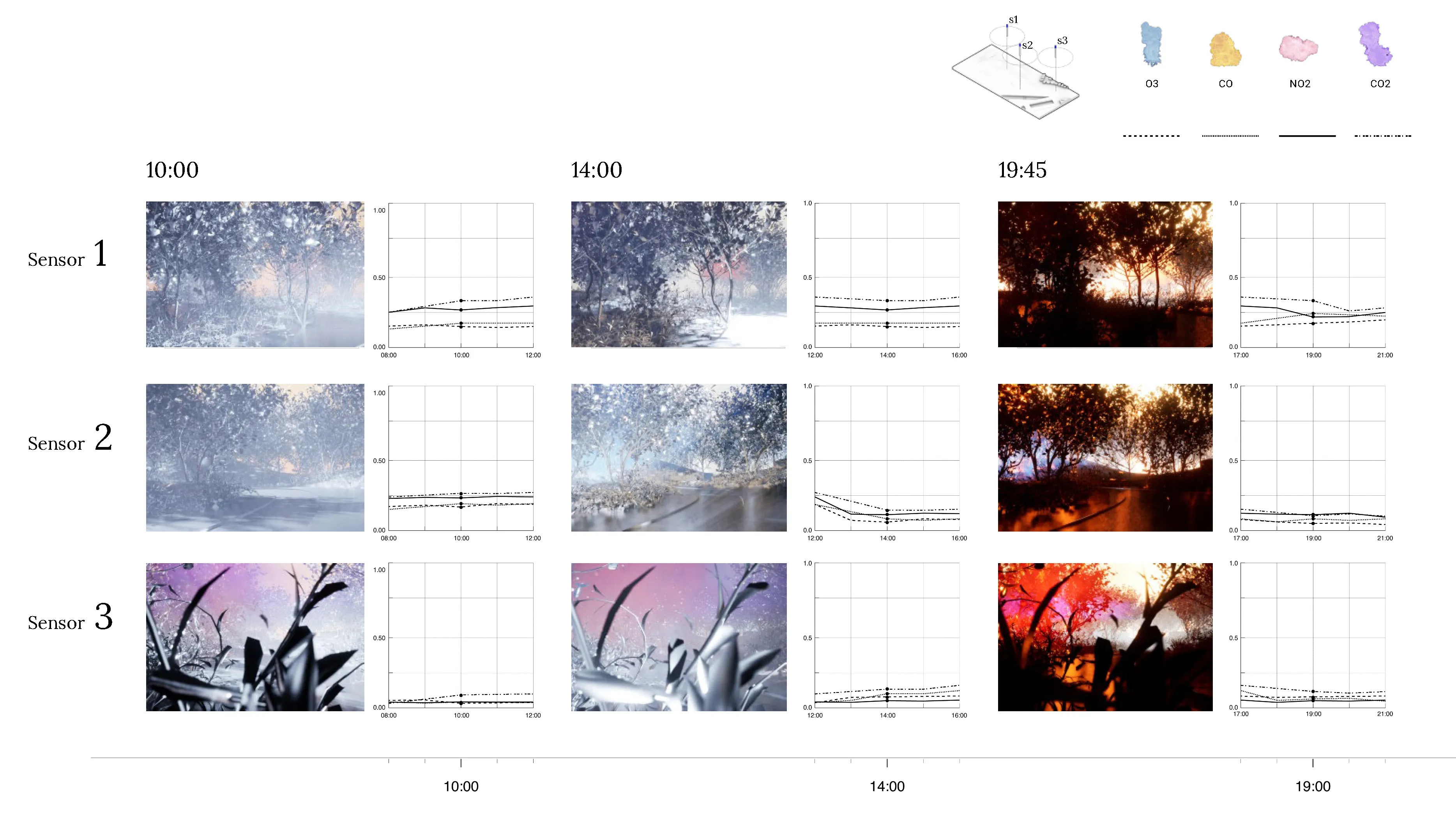
The second site studied is an edge condition between natureand infrastructure. The Harvard Arnold Arboretum adjacent to the Forest Hillsbus and train stations. The three sensors placed beginning from the streetintersection and into the wilderness of the Arboretum.
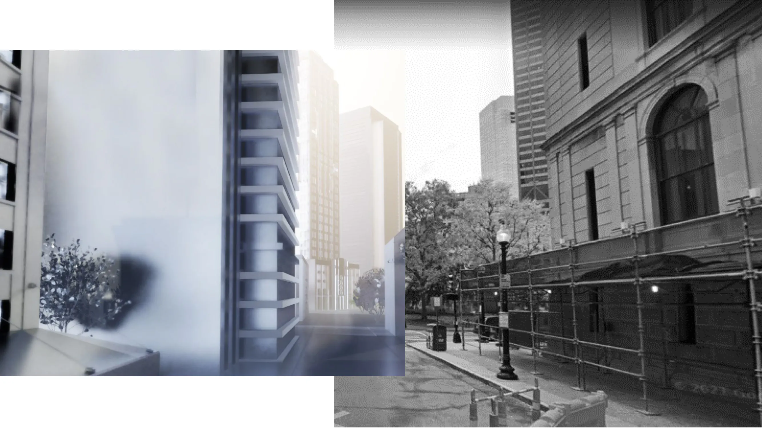
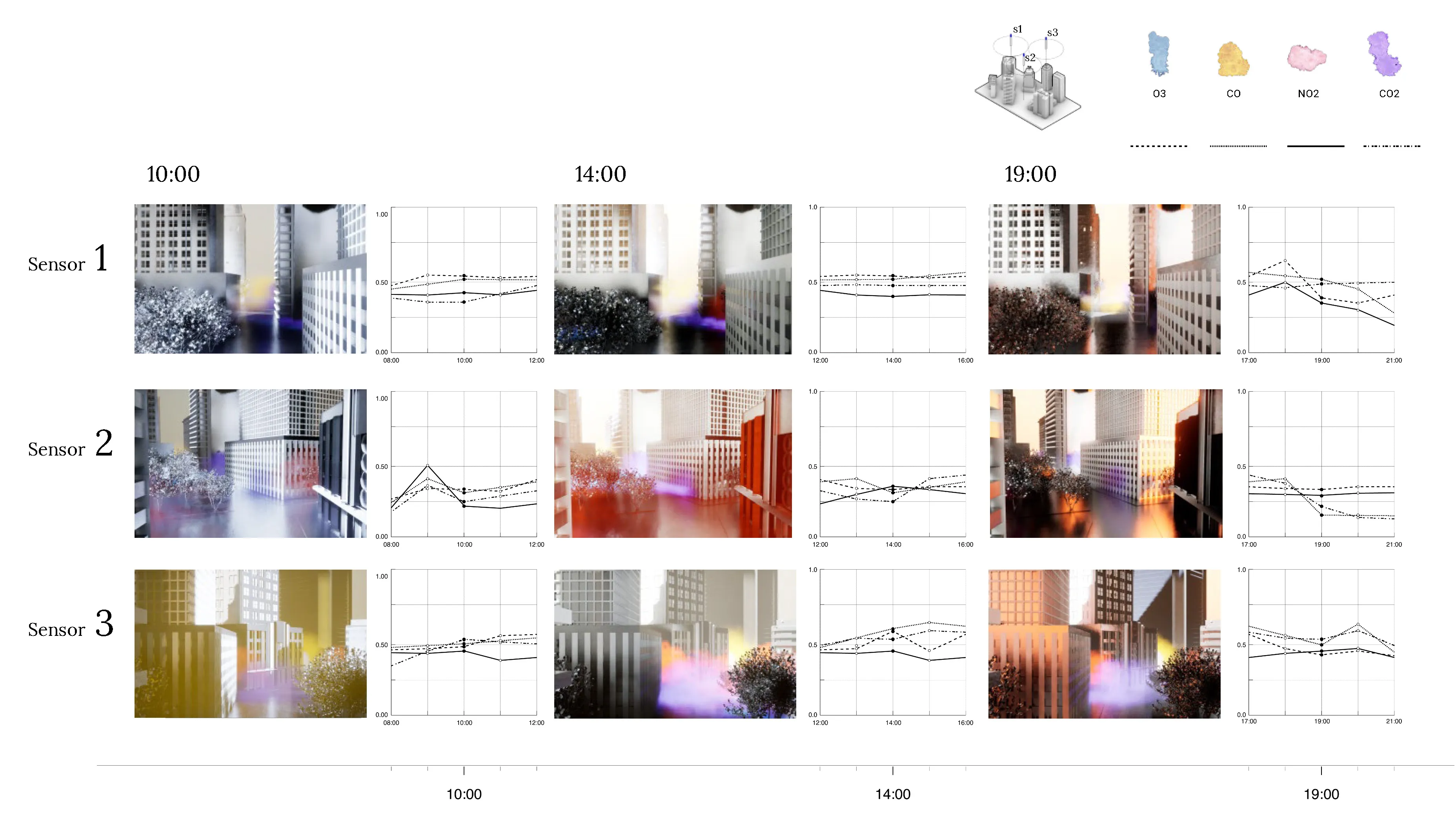
The third site is Downtown Boston, where reflecting on learningsfrom the 1973 Dabberdt’s Urban diffusion simulation for carbon monoxide inurban canyons by the Stanford’s Environmental Lab, sensors are placed alongdifferent sides of the canyon to understand the disparity between readings withinone small urban area.
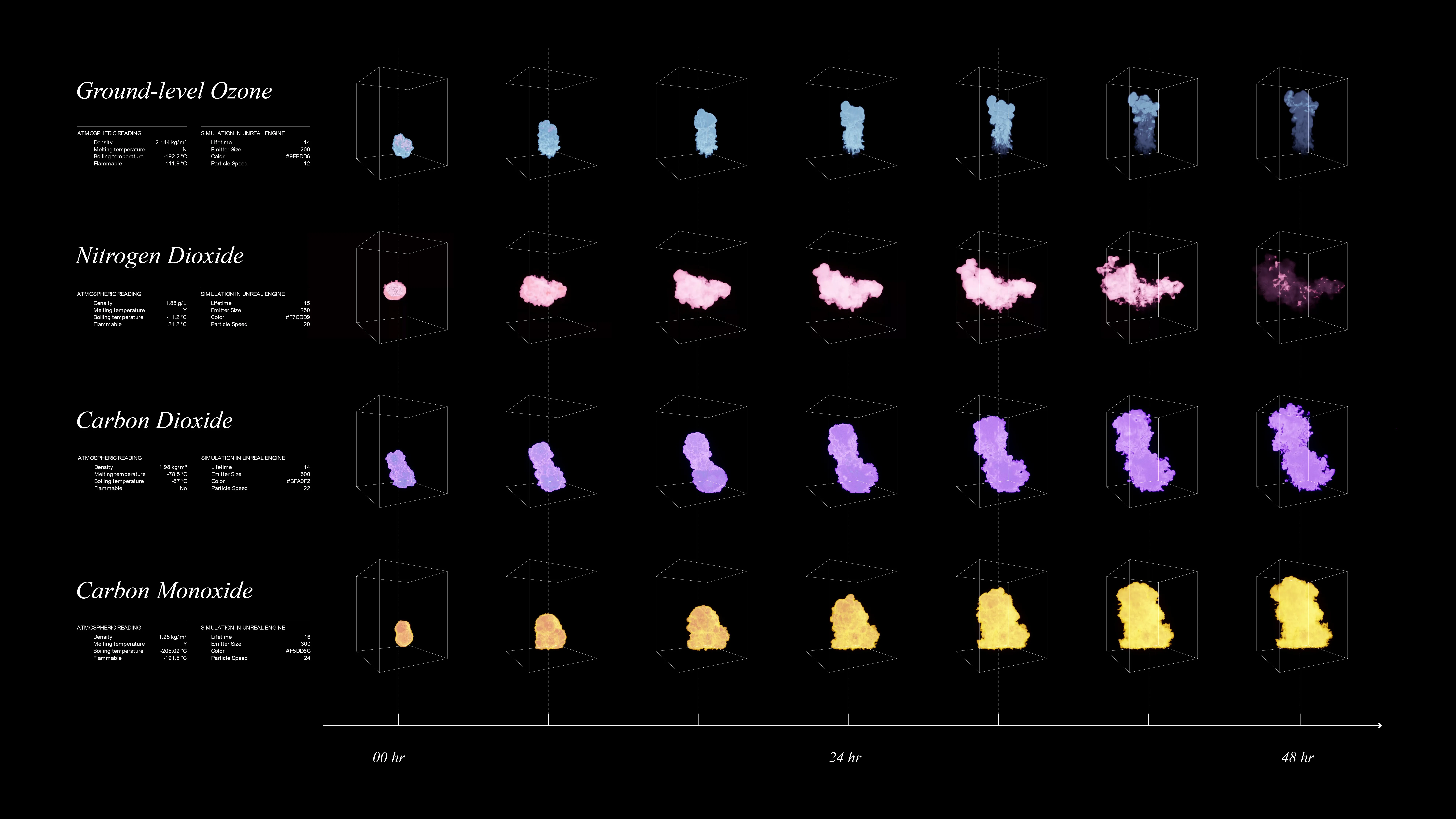
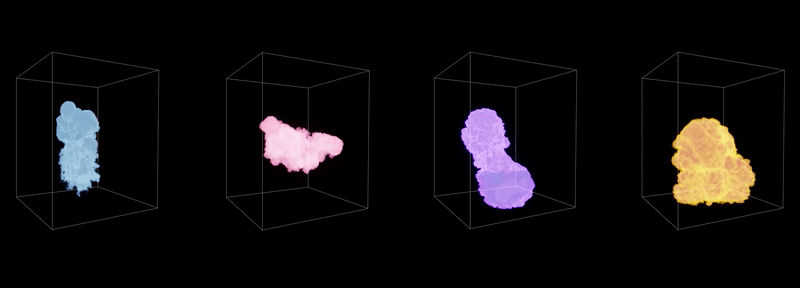
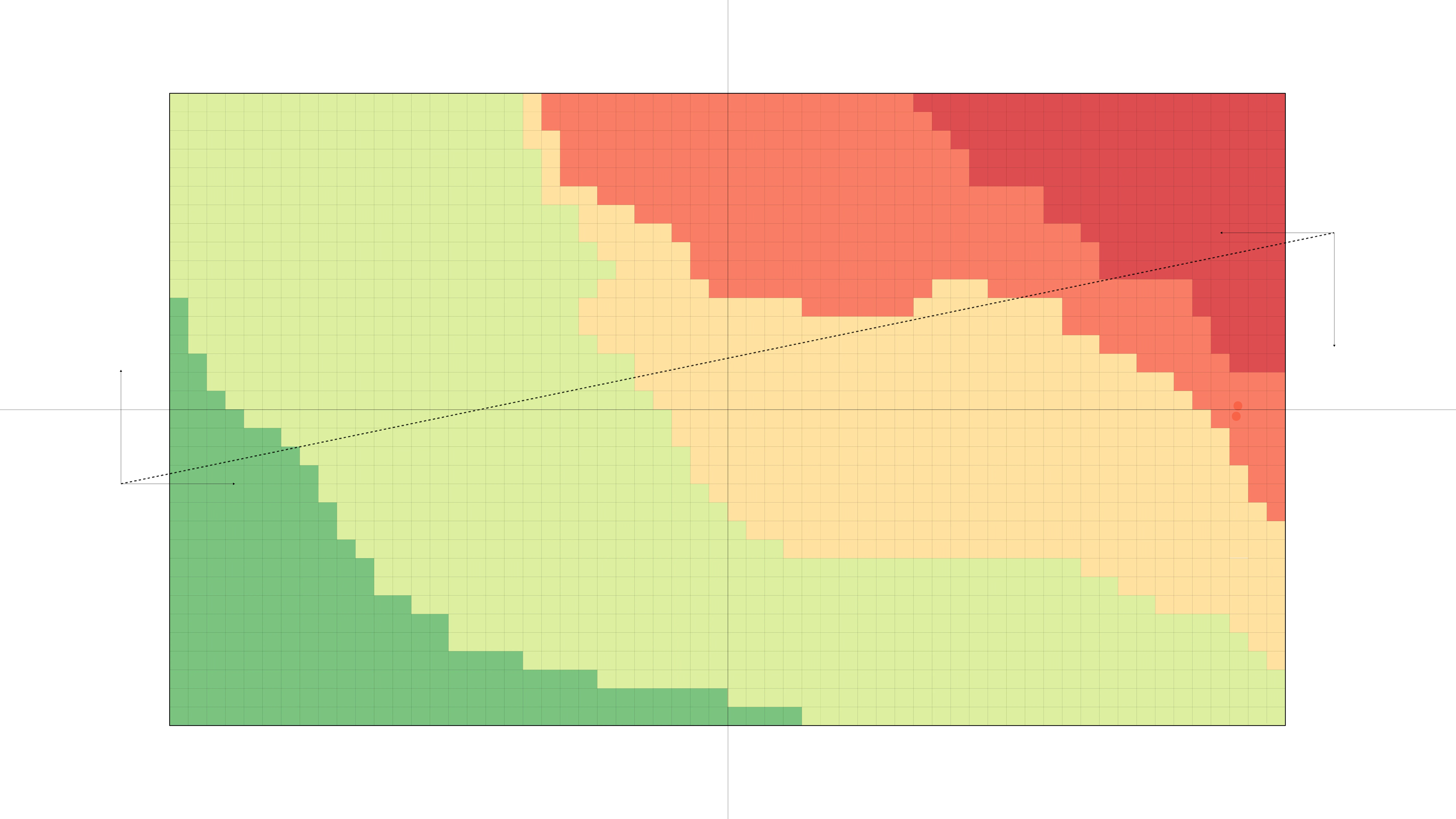
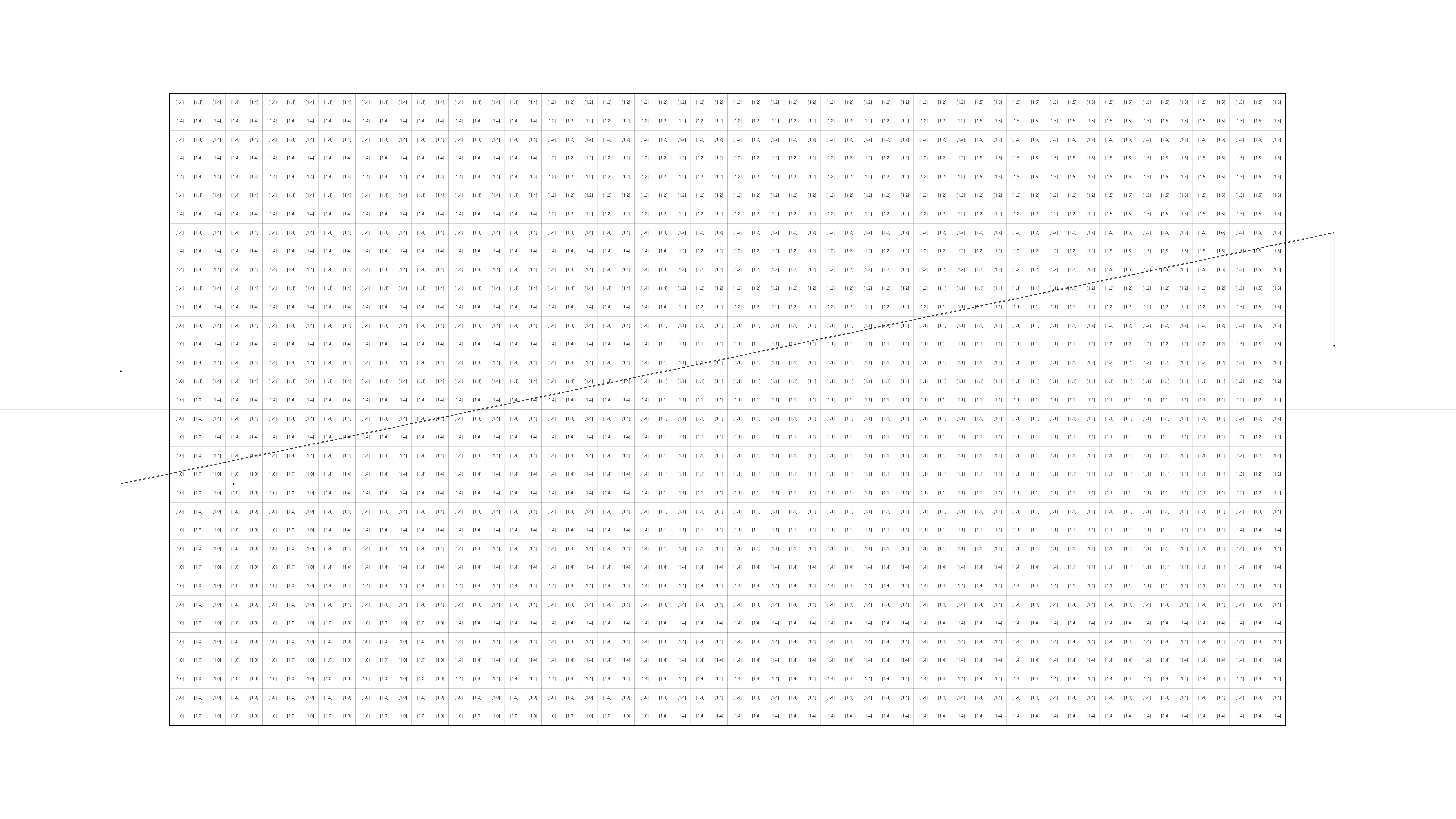
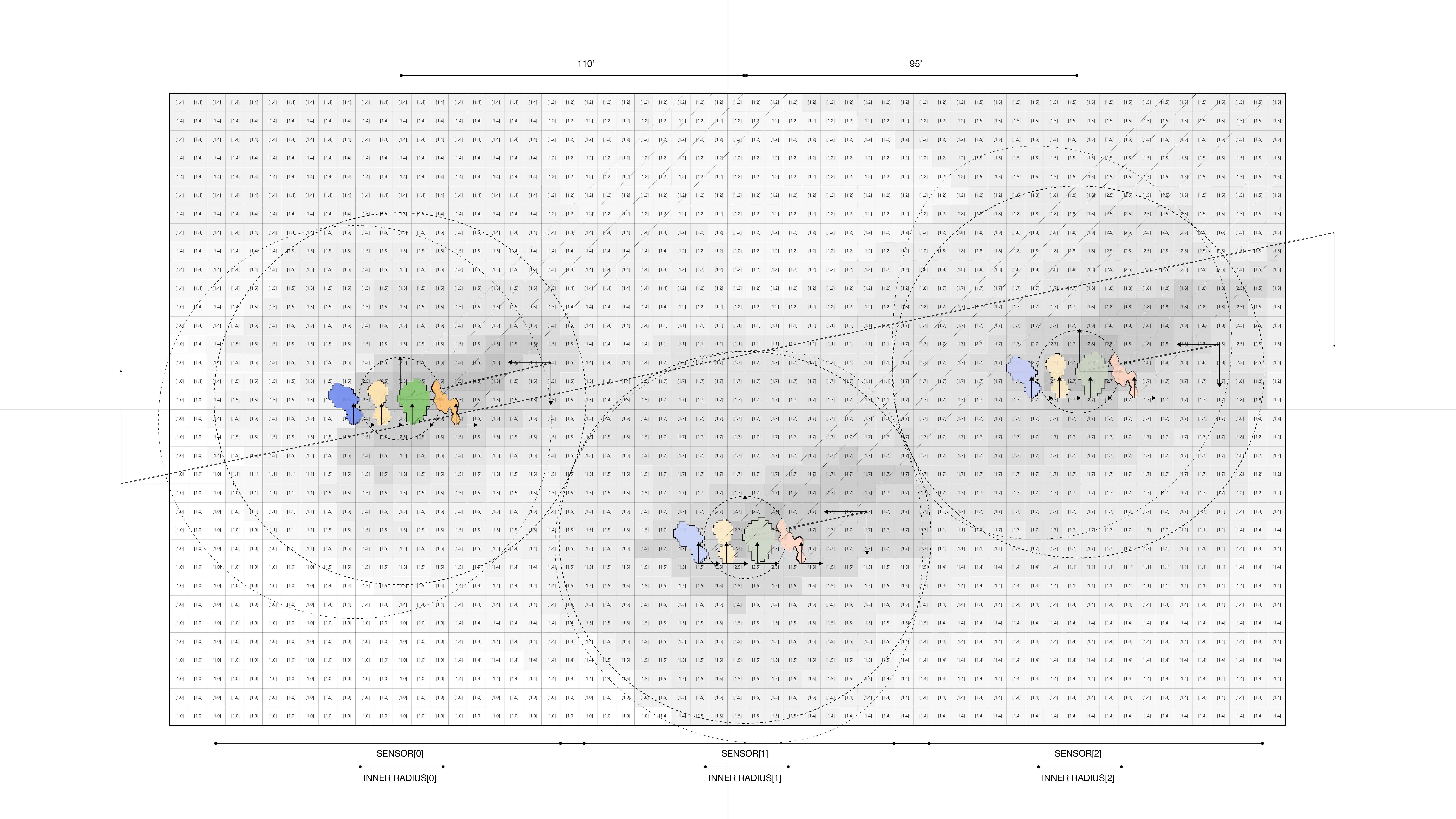
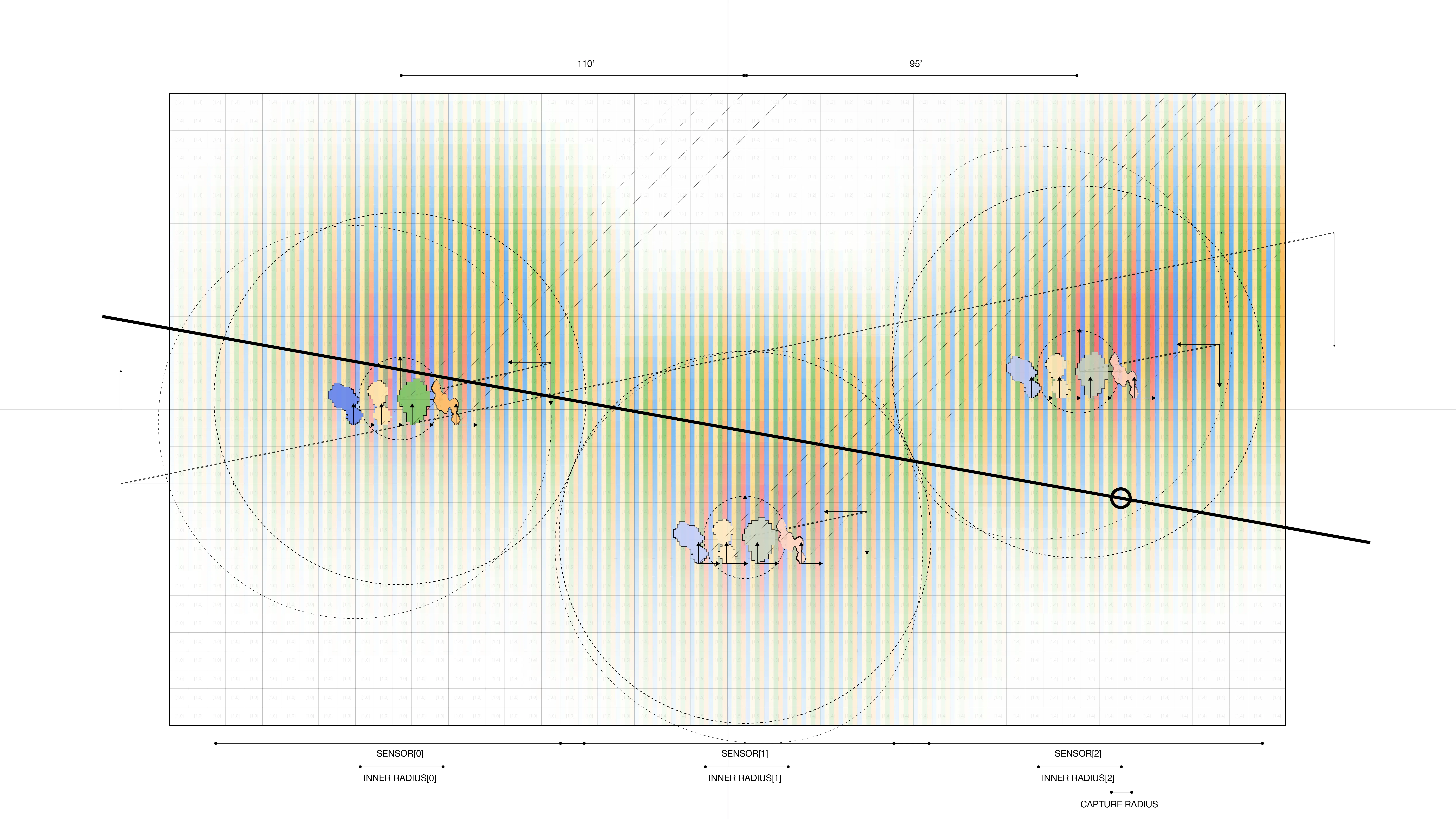
To simulate the effect if four gases, we collect informationon the characteristics of these gases in real world open-air scenarios. Thefour gases: Carbon Dioxide, Carbon Monoxide, Ground-level Ozone, and NitrogenDioxides. The features are color, density, flammability, melting and boilingtemperatures. In simulation, these behaviors are translated into decay,movement vectors, and color for each of the gases.
As shown below, the simulation of each of the gases in unrealengine 5.0 using the niagra systems.
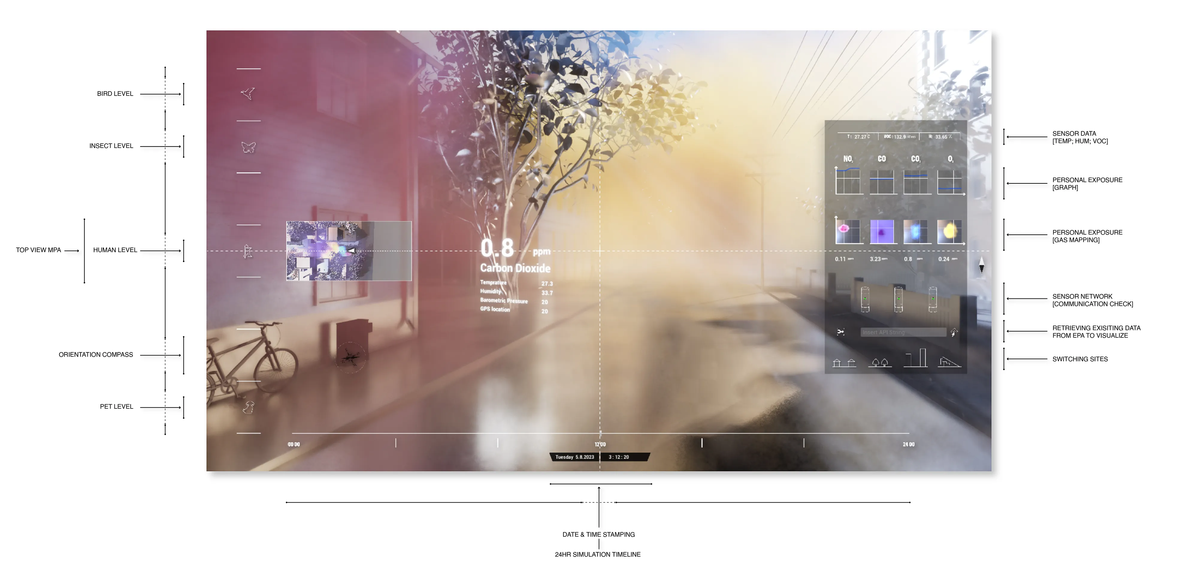
We design a standalone desktop application / interface thatprovides users with several features including:
Testing at each of the sites with three sensors in real-time.
In order to activate the 3D environment and capture personal-exposure levels in a low computational power, a stack of several mathematical layers were developed on a two-dimensional plane.
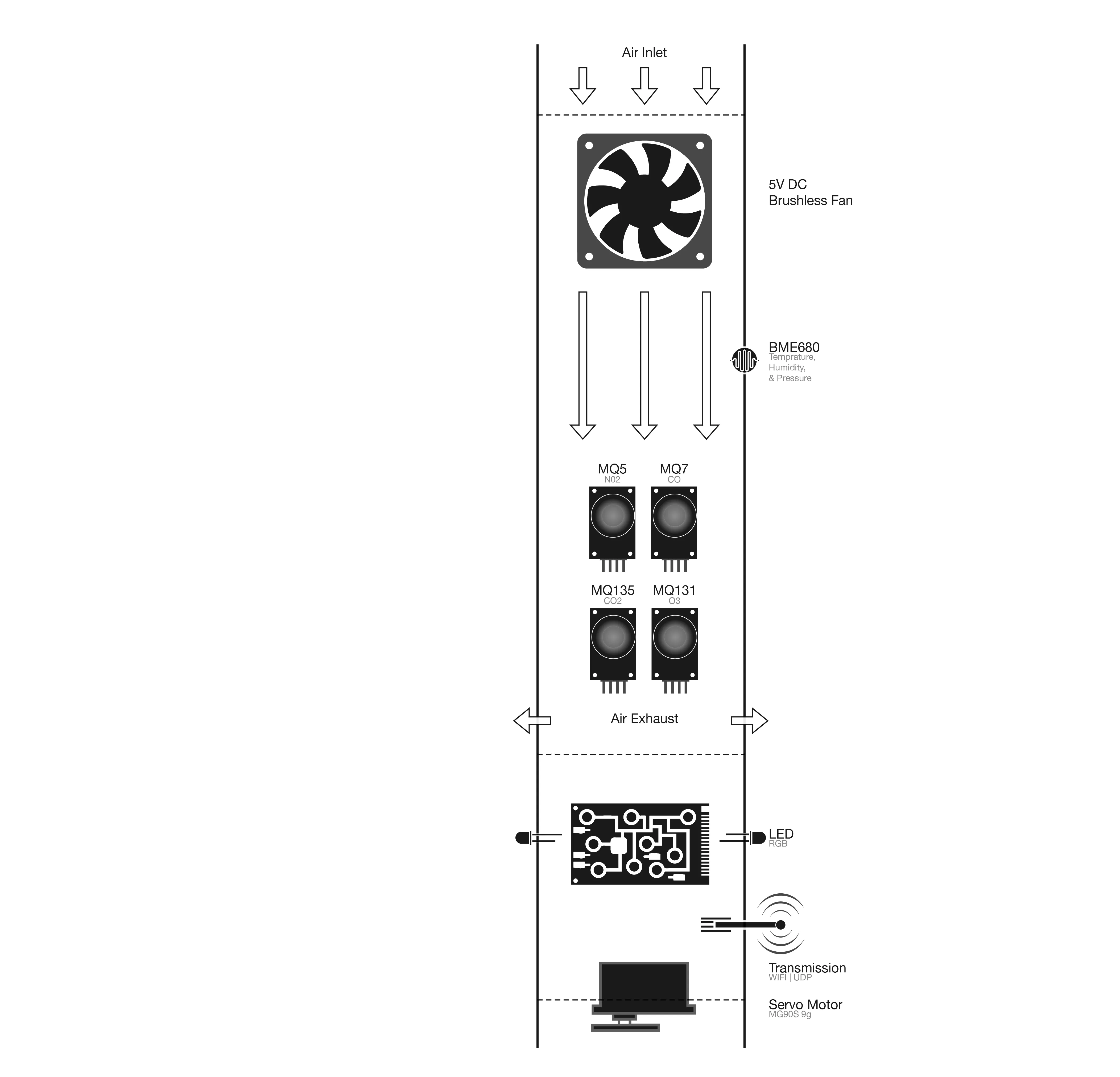
Calibrating low-cost custom air sensors by synchronizing and collecting data in real-time from the Environmental Protection Agency (EPA) Tthen comparing them against
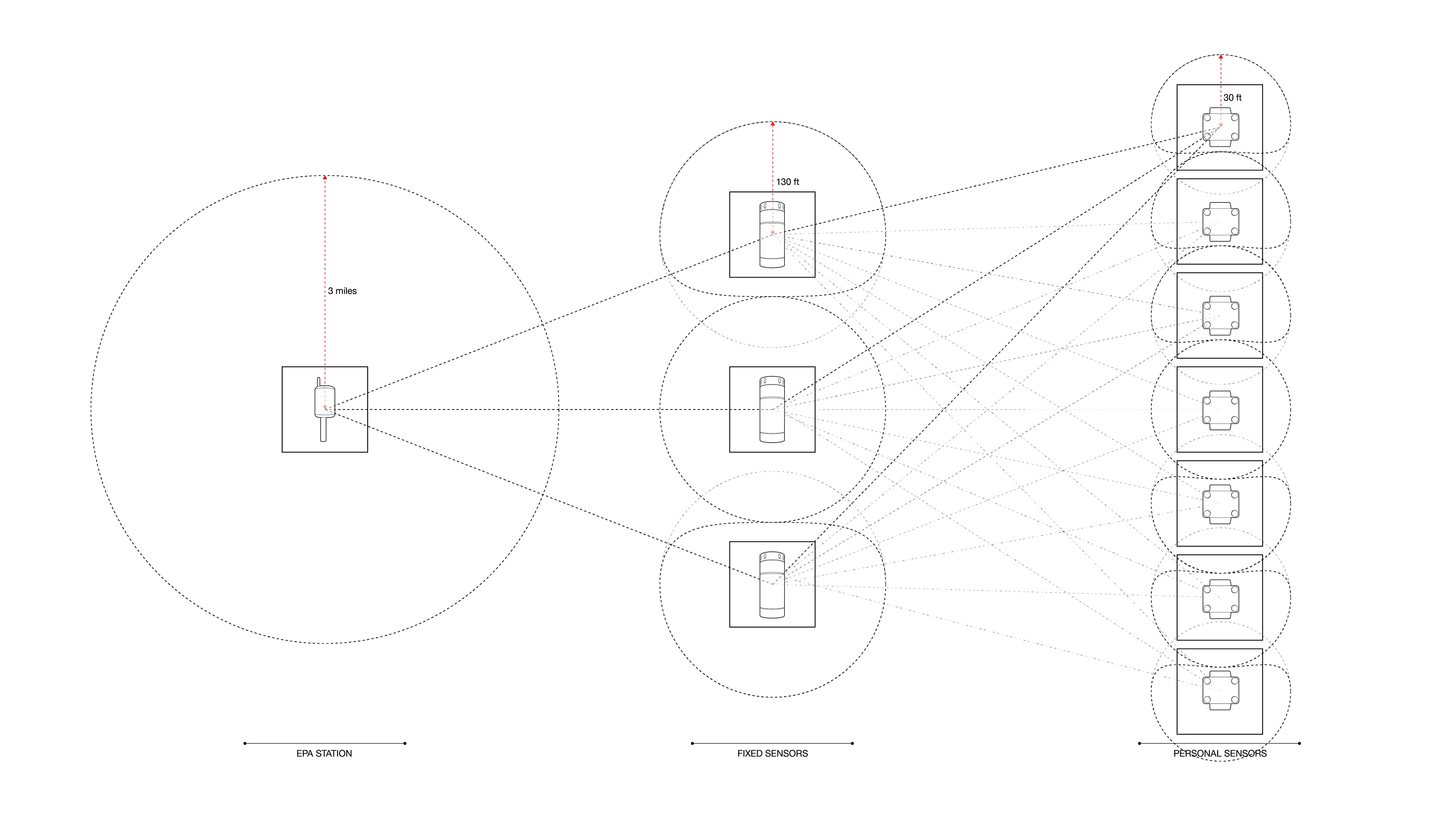
Onsites (Sumnert St, Harvard Arboretum, Downtown Boston) testing.
All images, video, and text courtesy of Deeplocal (Pittsburgh, PA).


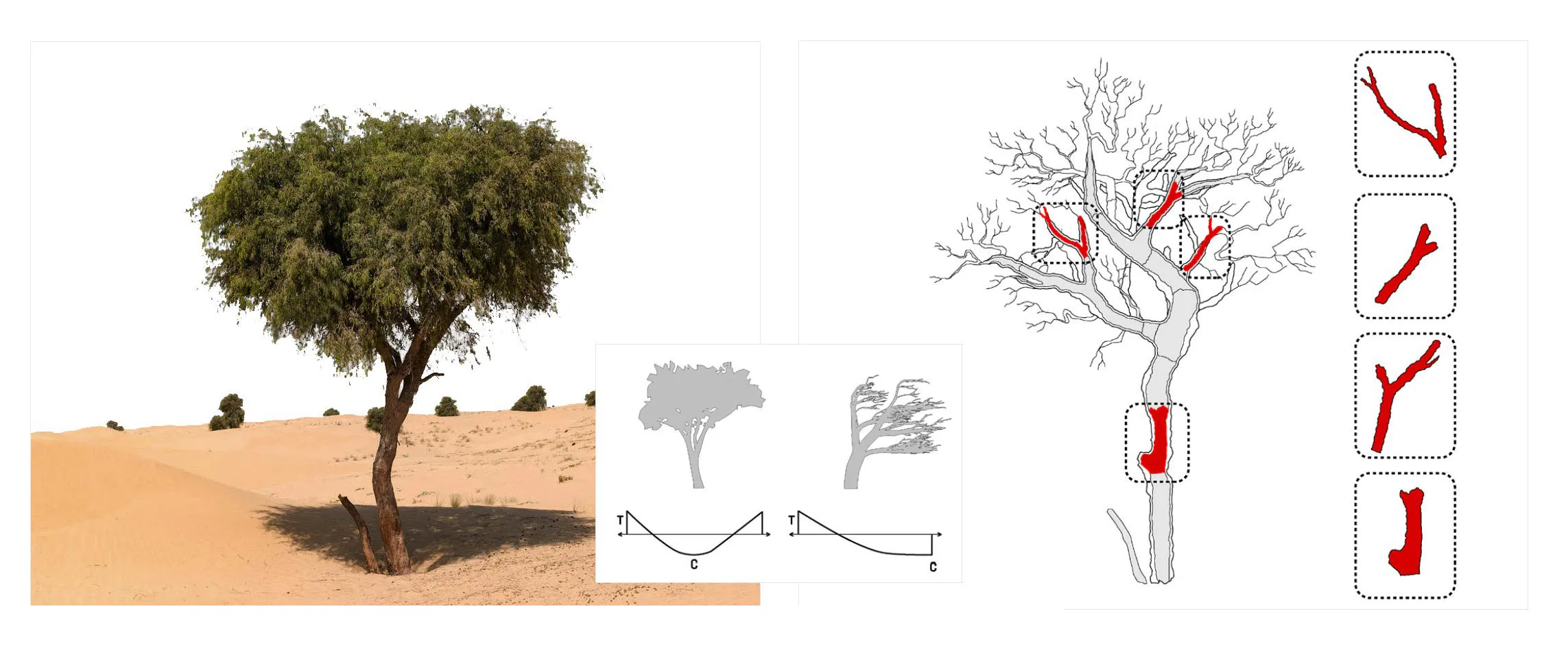
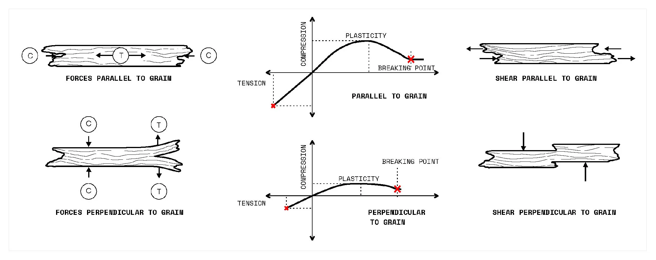
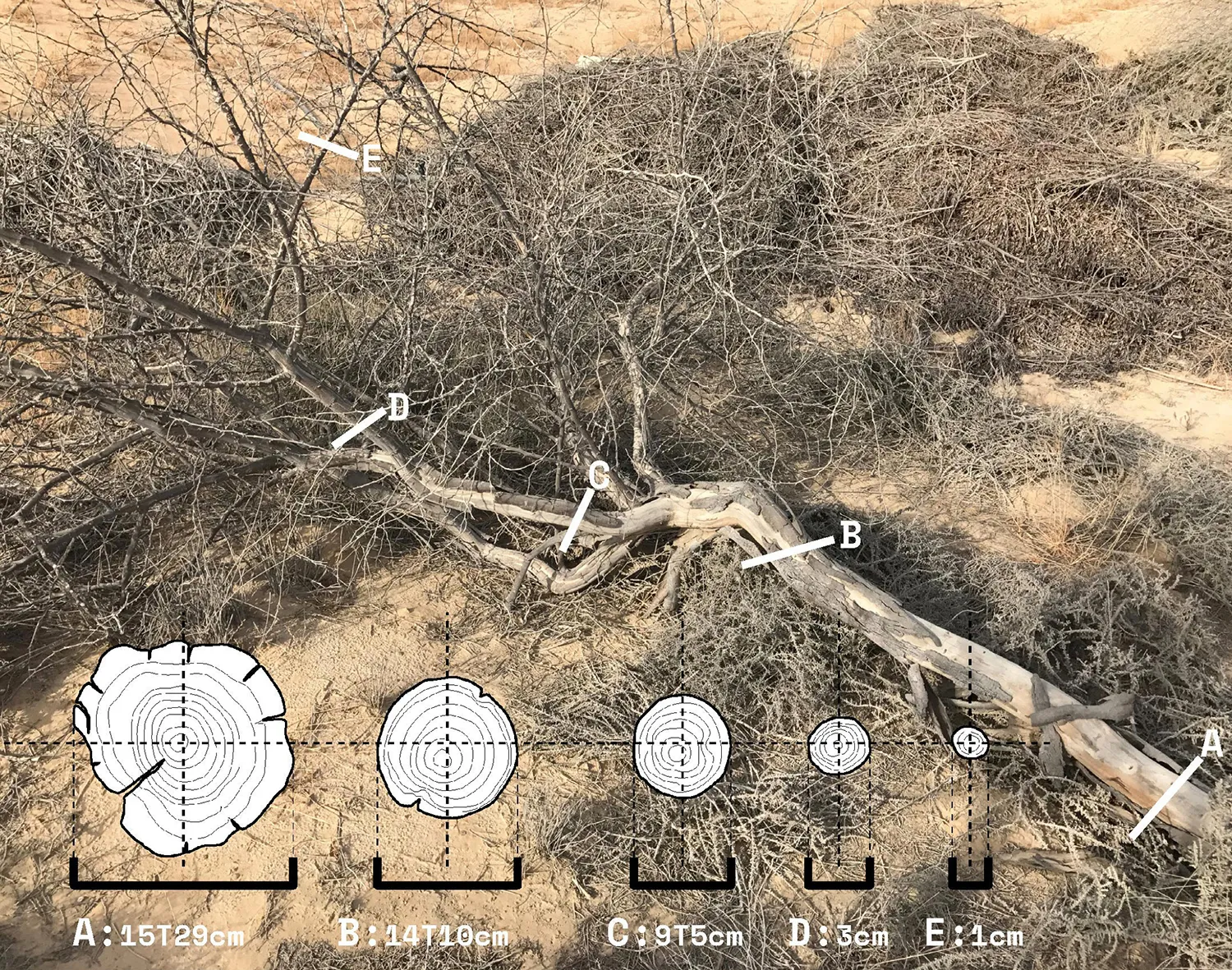
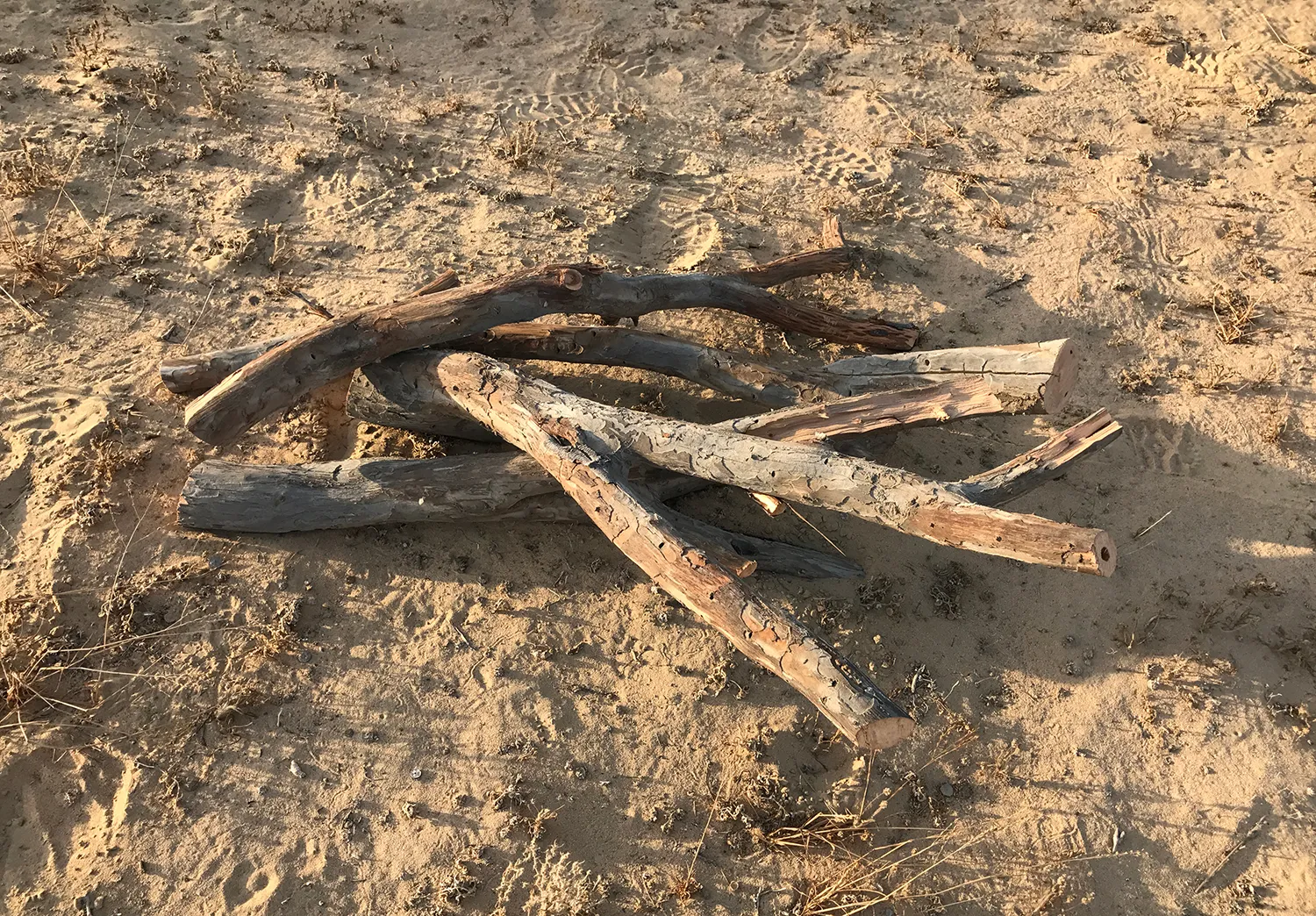
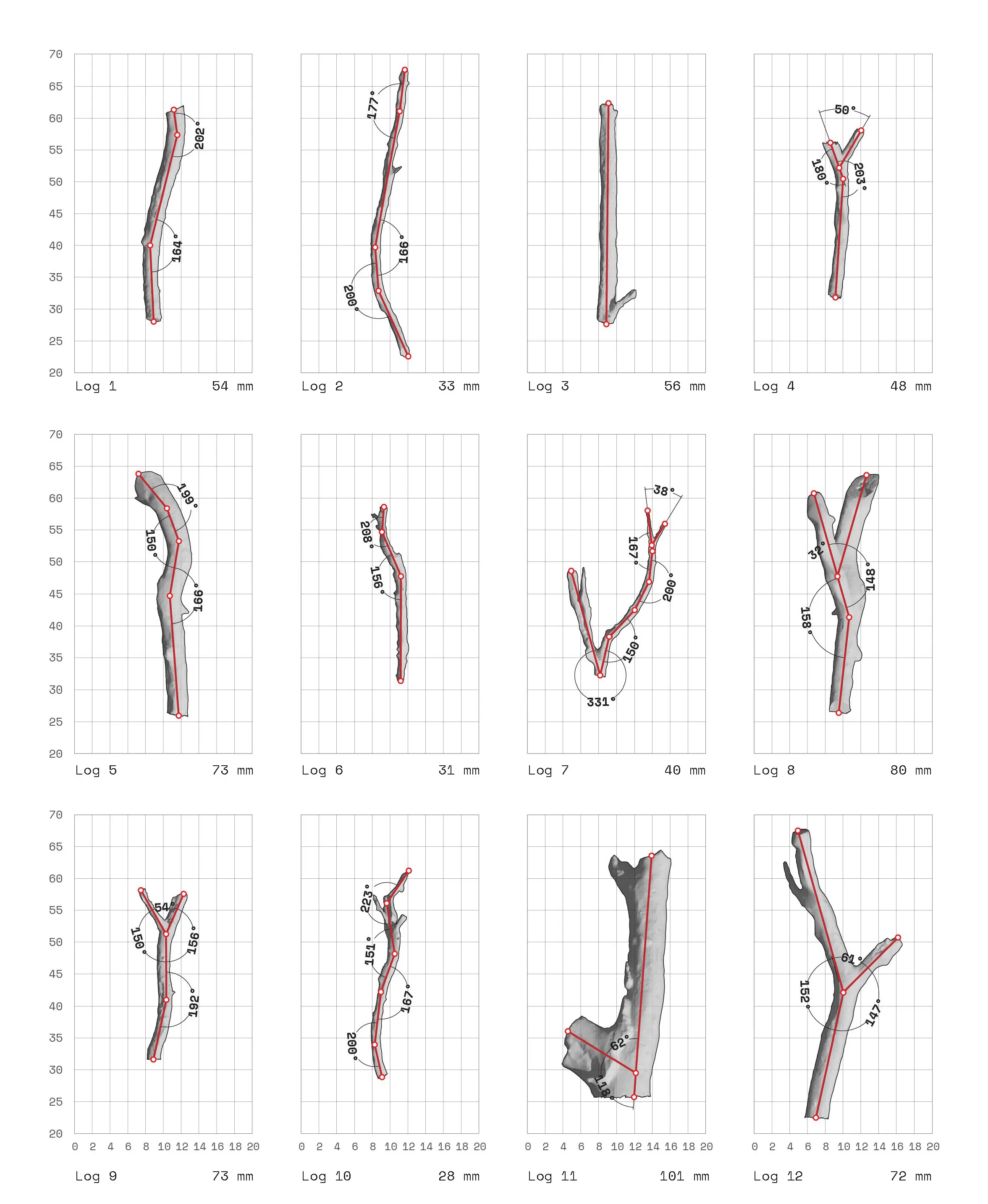
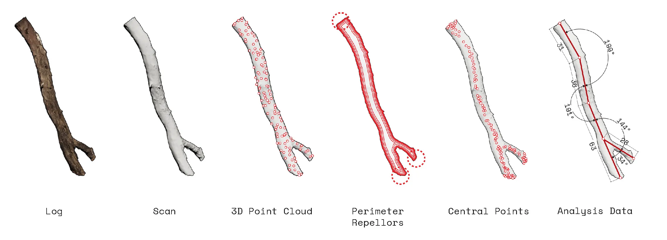
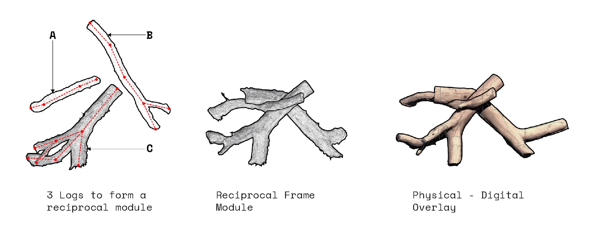
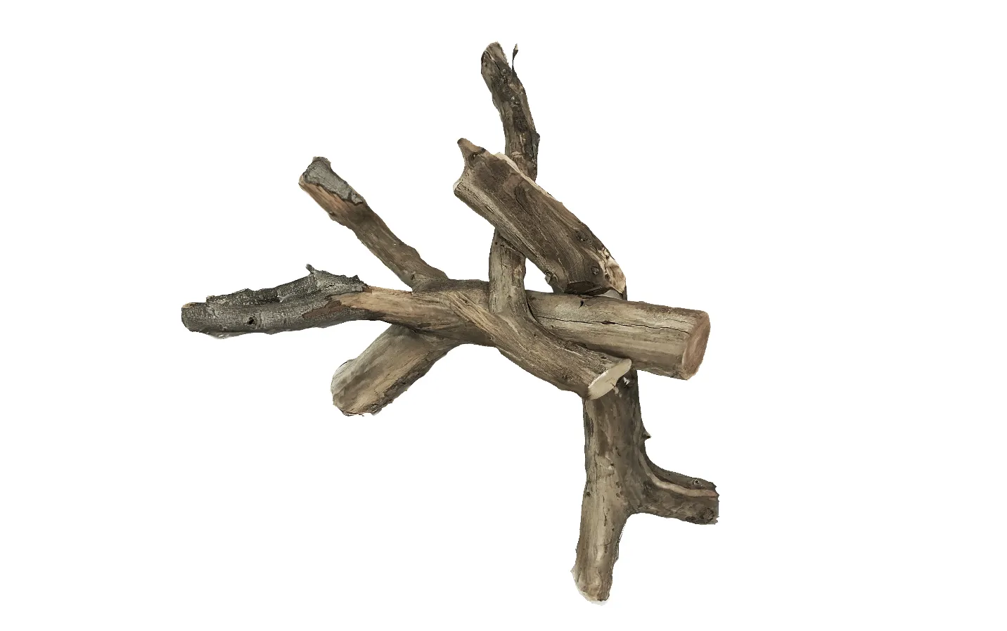
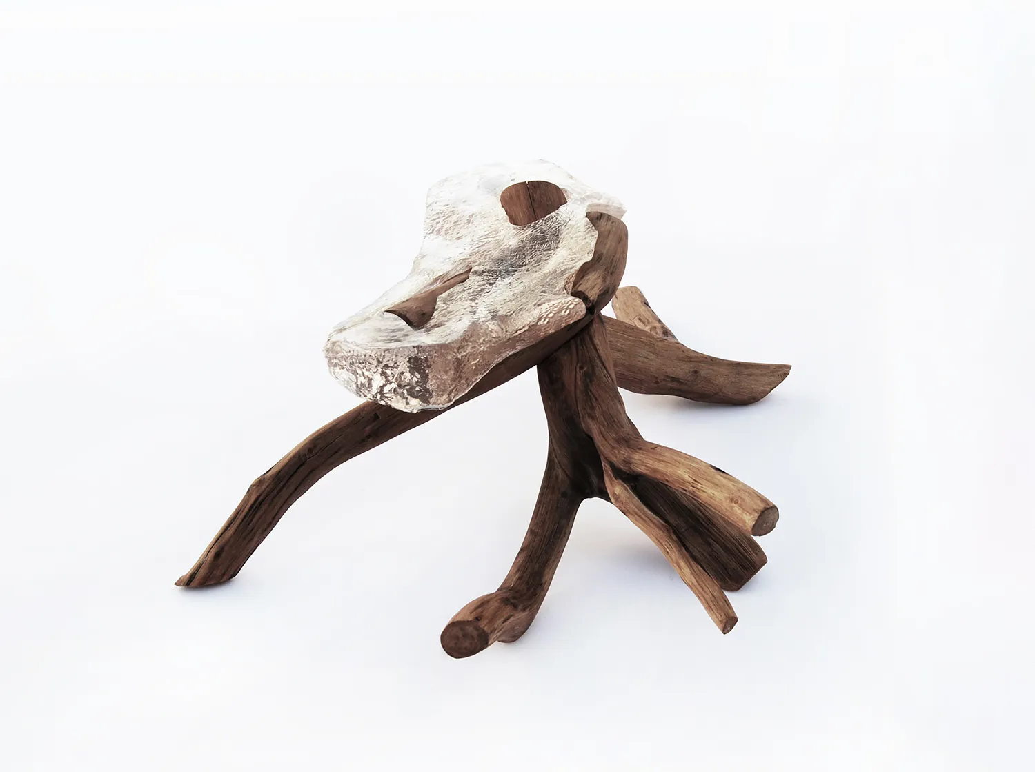
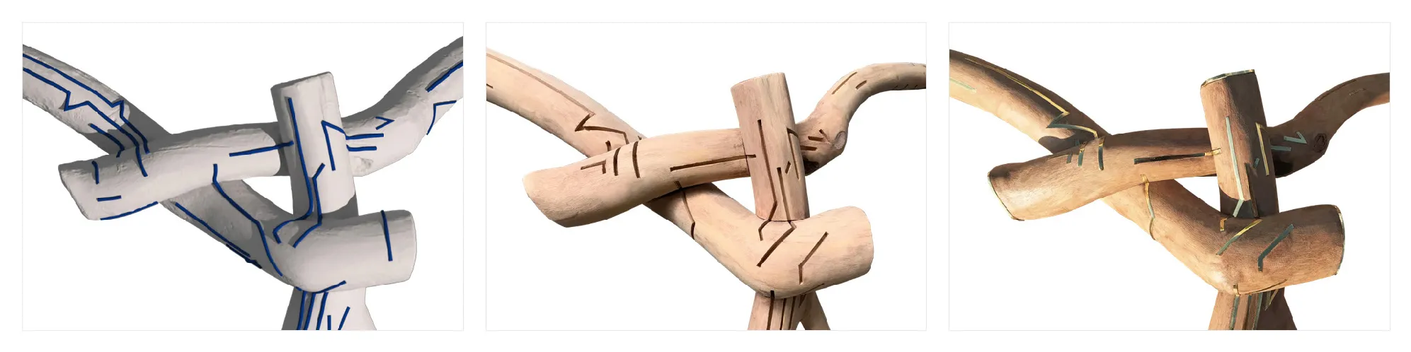
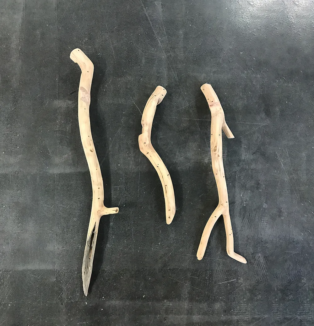
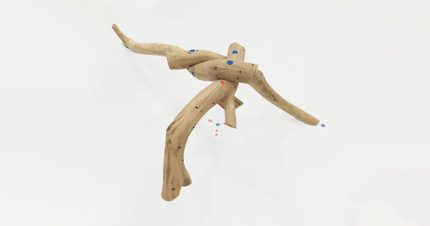
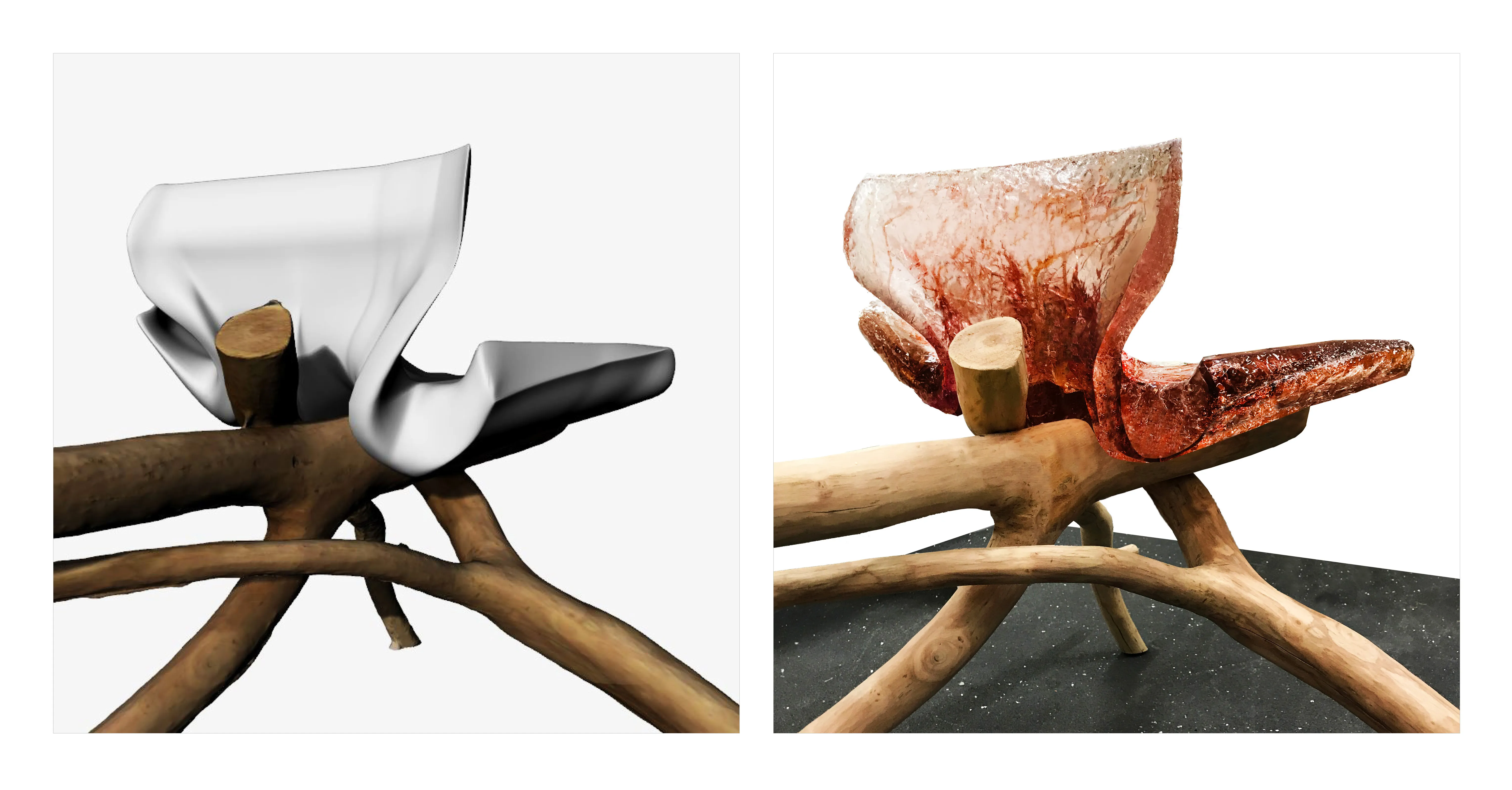
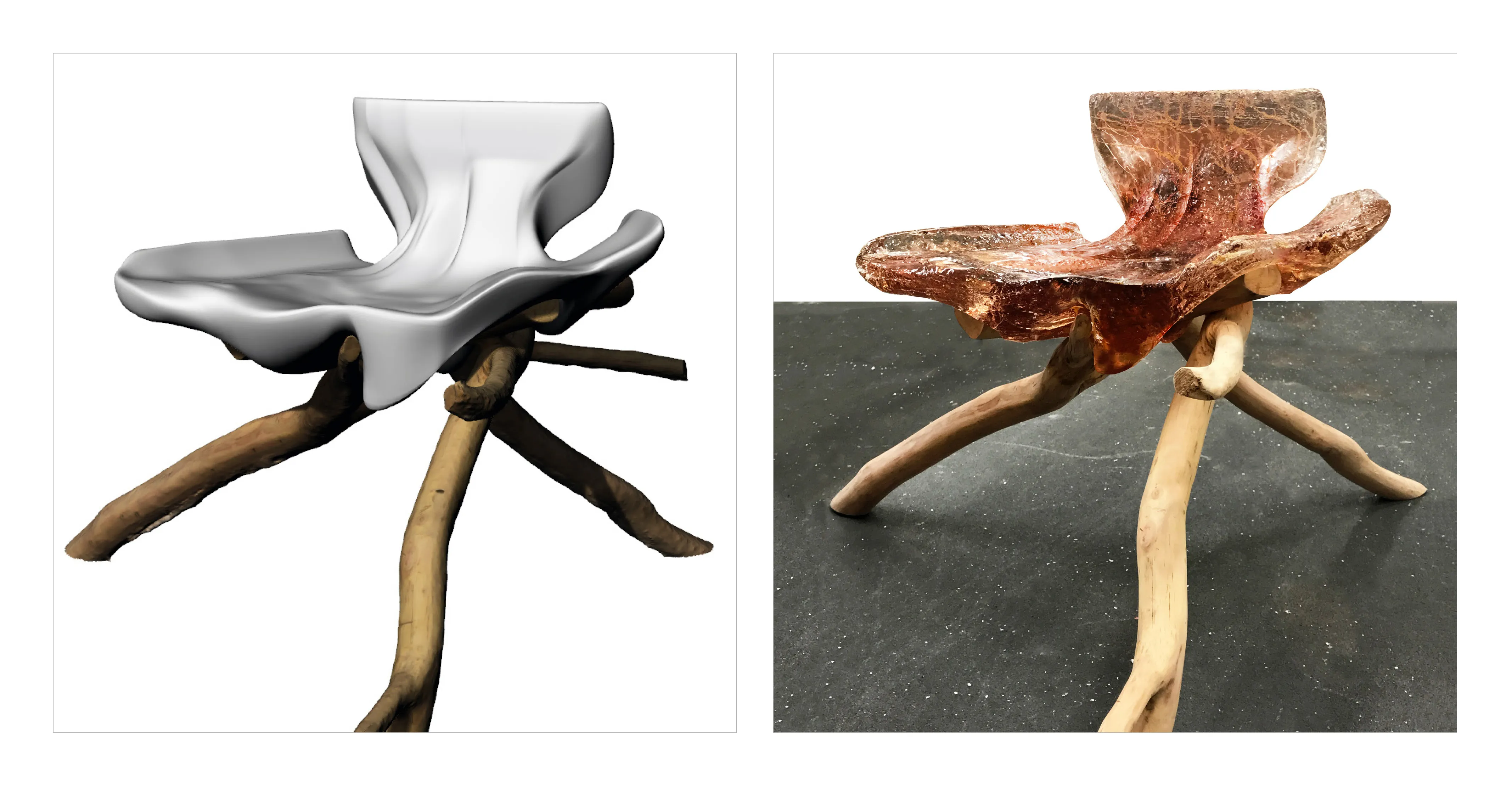
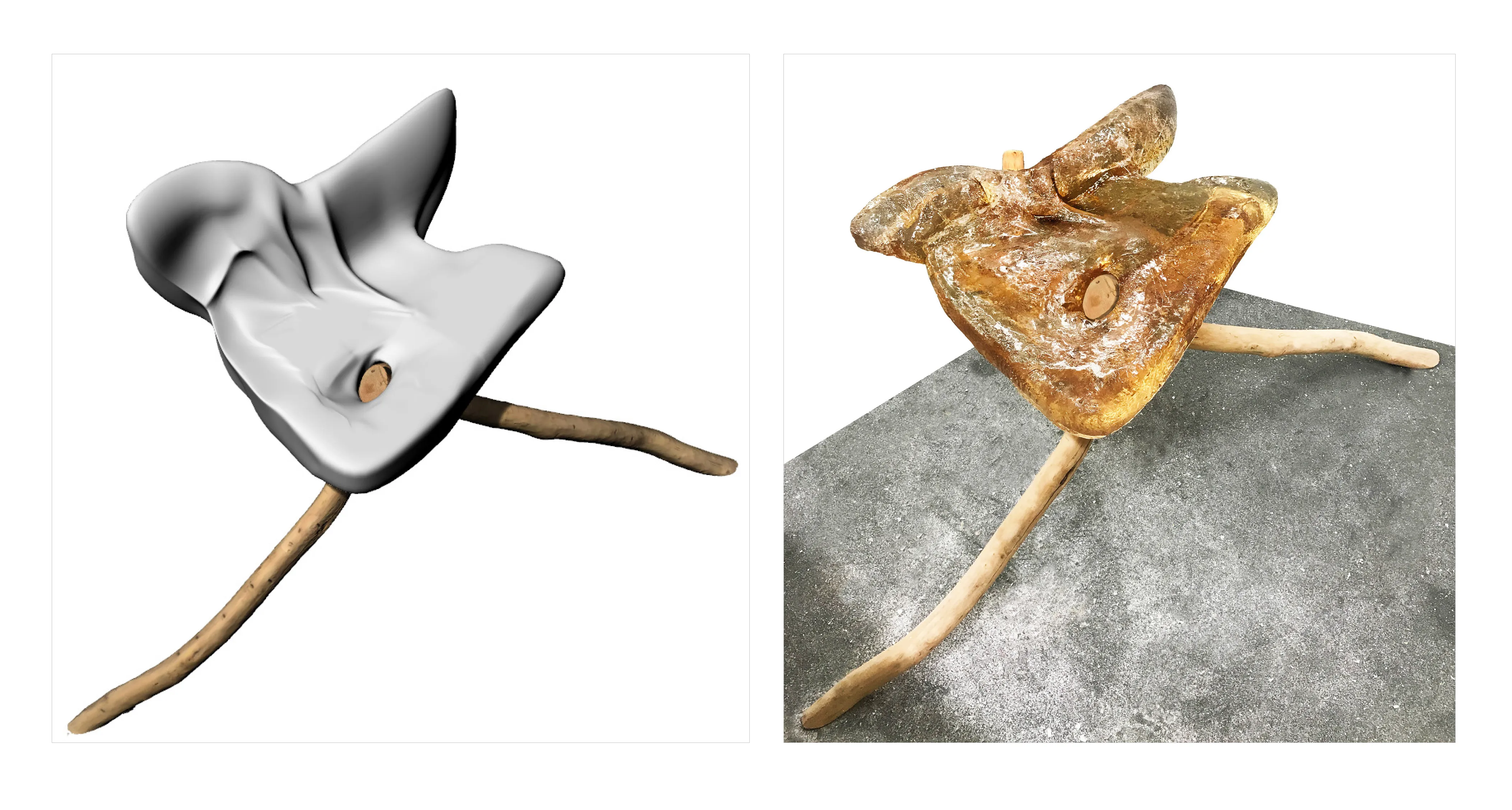
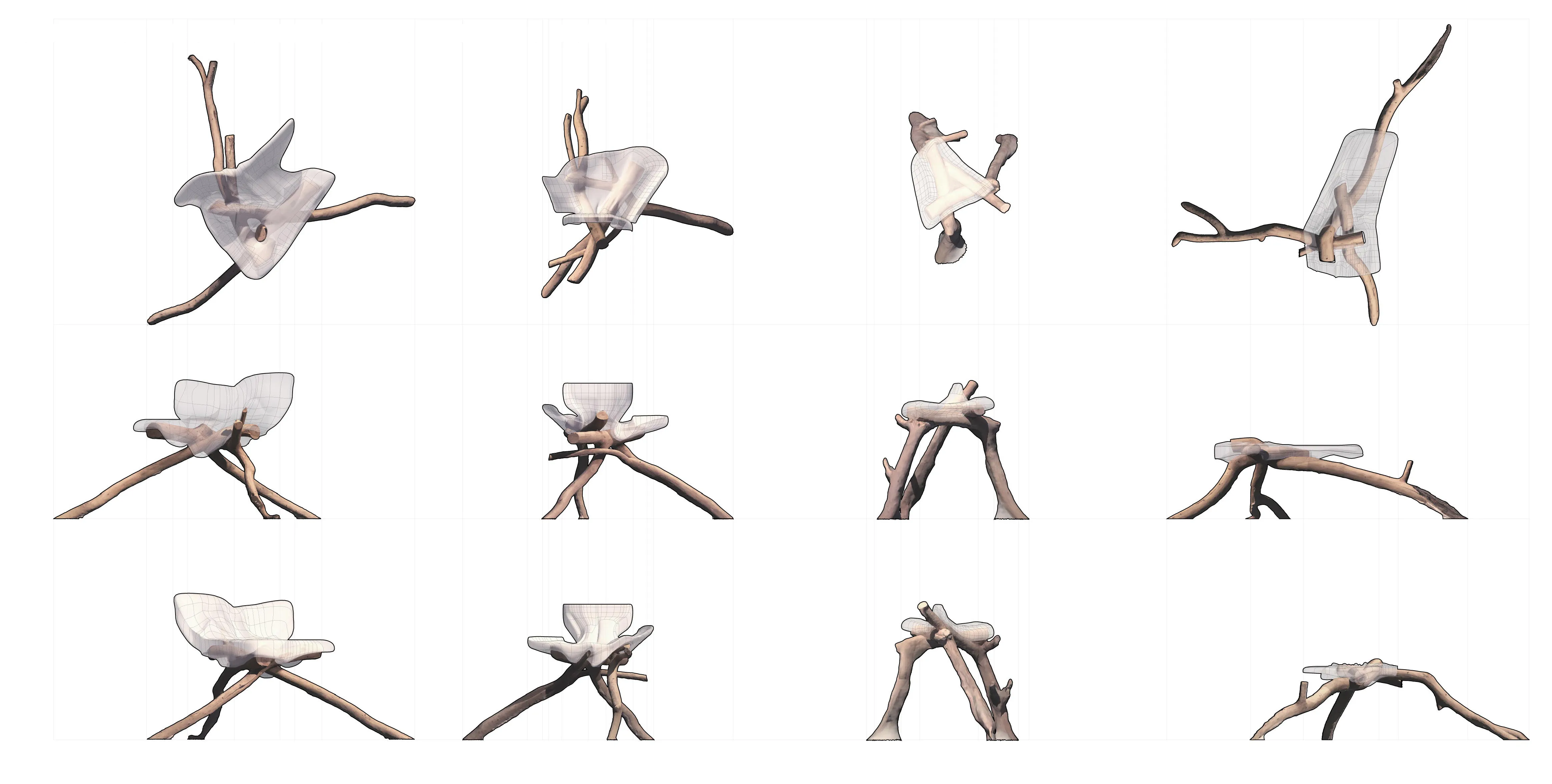
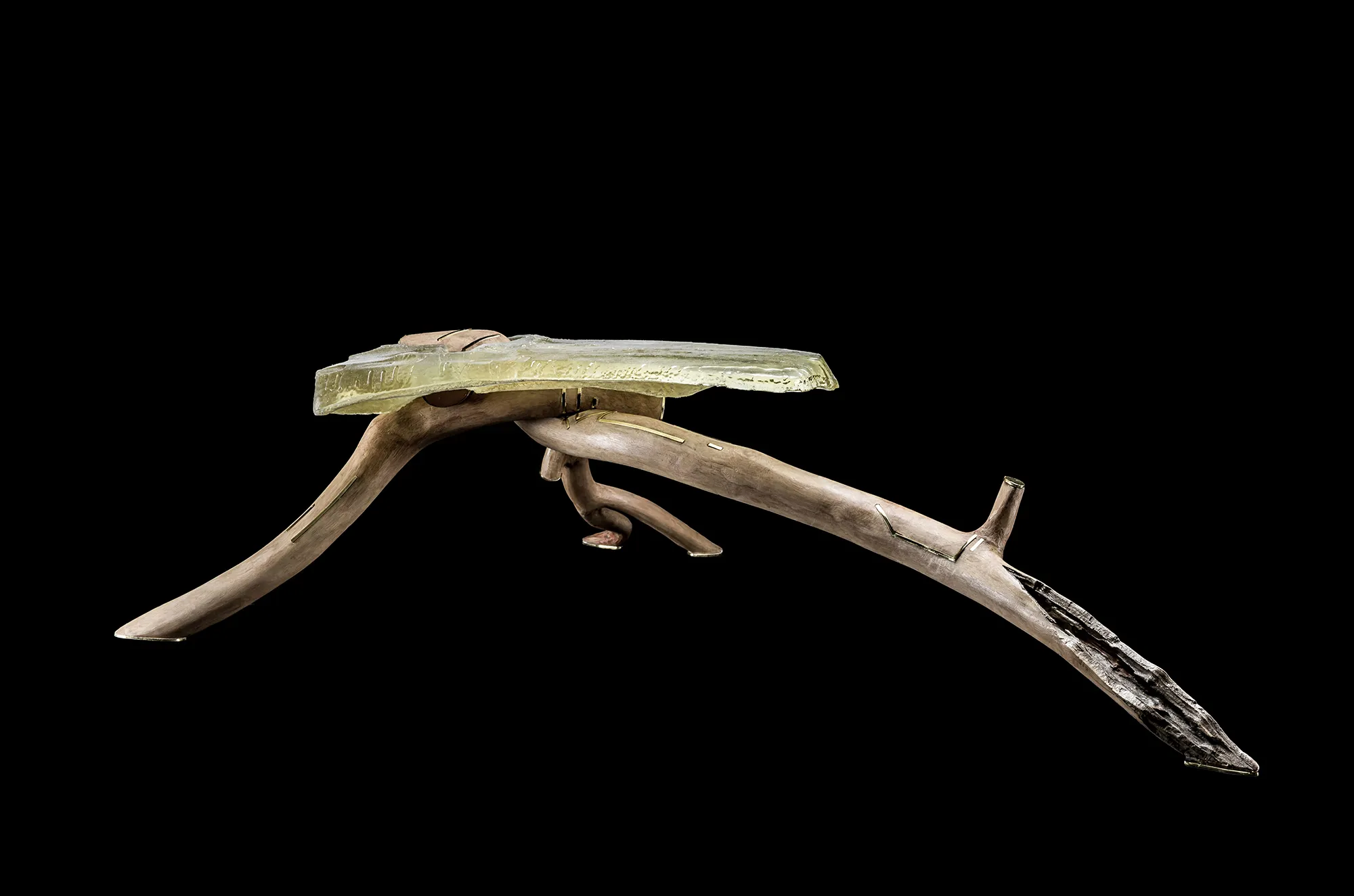
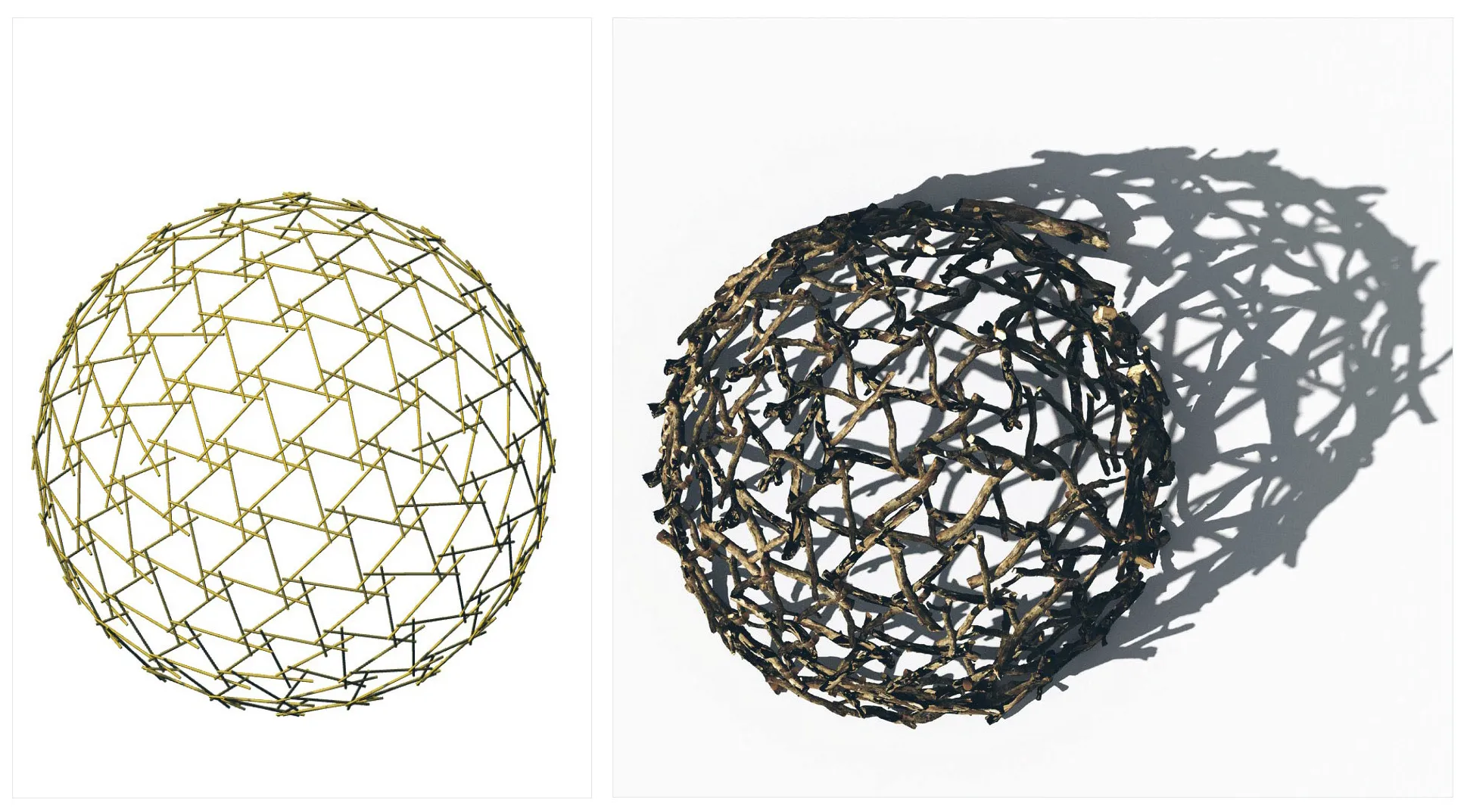
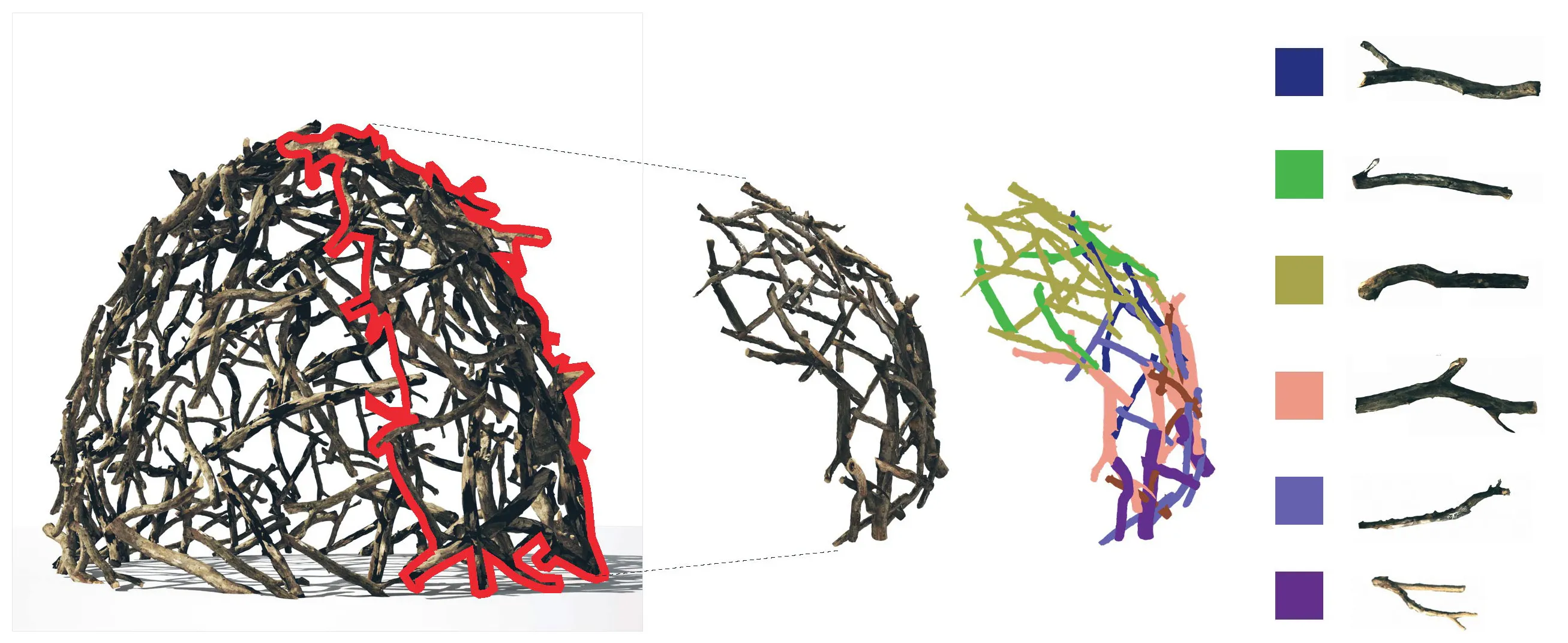
The story of a fall 'ghaf' tree within the UAE's desert scape.
Generative Abstraction of Average Paths & Kinks.
Project information coming soon.
Project information coming soon.
Project information coming soon.
Project information coming soon.
Project information coming soon.
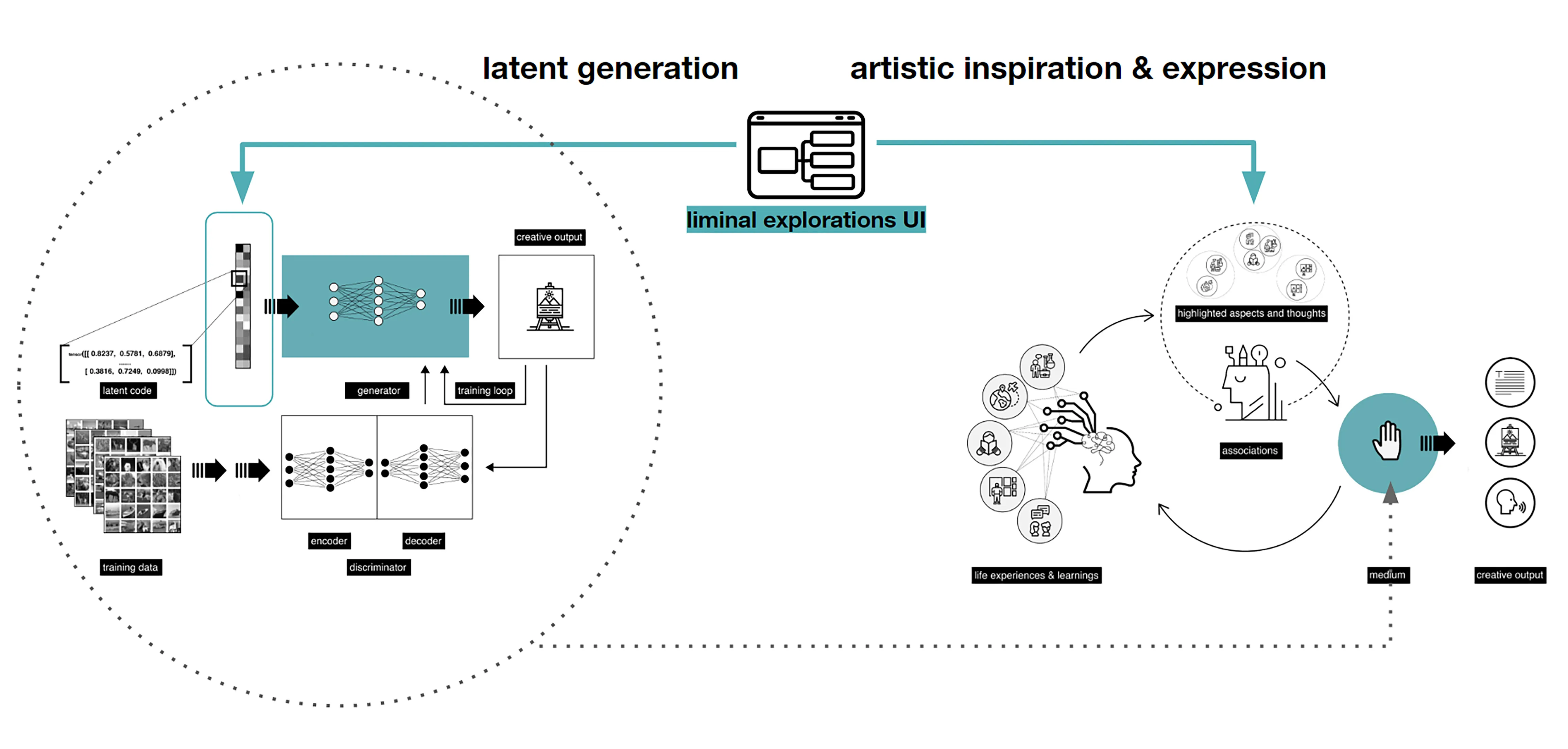
Despite the earlier apocalyptic predictions about workers being replaced by intelligent machines as Artificial Intelligence (AI) finds its way to businesses, the course of AI seem to be taking a new tactic: actively searching for ways to collaborate with human. Human intelligence paralleled with AI capabilities and and computational speeds, is a novel gateway to modern design tools. Humans and AI actively enhance each other’s complementary strengths: the leadership, teamwork, creativity, and social skills of the former, and the speed, scalability, and quantitative capabilities of the latter [15]. Unlike the commonly know Human-AI interaction, collaboration involves a mutual goal understanding, task co-management, and shared progress tracking [14]. In a creative collaborative creation process, human-AI collaboration could occur in multiple forms. For example, humans could initiate a design workflow with a first parameter that resembles an intent, from which an AI model could begin to complete, suggest or analyze the content giving live feedback that would enrich the process. The user then navigates through the option to steer the next steps. Using reinforced learning techniques, a reward and penalty system is implemented to curate the process as the AI model continues to learn from the human input. Therefore, prototyping faster, with wider range of design exploration, and efficient analysis. A similar example, when an AI model transforms and visualizes simple creations done by humans in real time into new more complex forms.
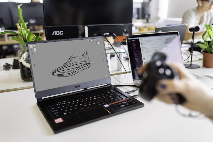
For many, sketching, which ranges from quick gestures to refined drawings, is a root step in any creation process. It has been predominantly flattened into a two dimensional surface, minimizing the many design information a simple gestural sketch could embody. The interactive design experience and process that is usually initiated with a ’sketch’ is further enriched by moving beyond two dimensional surface into three dimensional environment. Hence, space as a canvas of creative and interactive prototyping. Spatial 3D sketching has been for long limited to VR hardware and typically requires special hardware for motion capture and immersive stereoscopic displays. Recent advances in motion-tracking algorithms in smart phones, such as Concurrent Odometry and Mapping (COM) [10] and Visual Inertial Odometry (VIO) [8], enabled the utilization of mobile phones as a stylus and screen for mid-air 3D sketching. Mid-Air sketching using the mobile phone is a technique that enables designers and creators to draw virtual gestures or curves directly in the air in 3D. Unlike VR, AR allows users to author 3D sketches that are more directly linked to real-world objects or environments [7], making it a powerful tool for rapid prototyping.
Fologram is a mixed reality application for Rhinoceros and Grasshopper 3D that is compatible with HoloLens 2, HoloLens 1, iOS and Android [1]. It accurately positions digital content in 3D space, streams and interacts with models, working with gestures and markers, modelling and controlling data flow. Some of its most common use cases within the architectural space beyond visualization is overlaying fabrication instructions for complex and atypical systems. It allows for various levels of control of the geometry, layers and grasshopper parameters in real time through its interface.
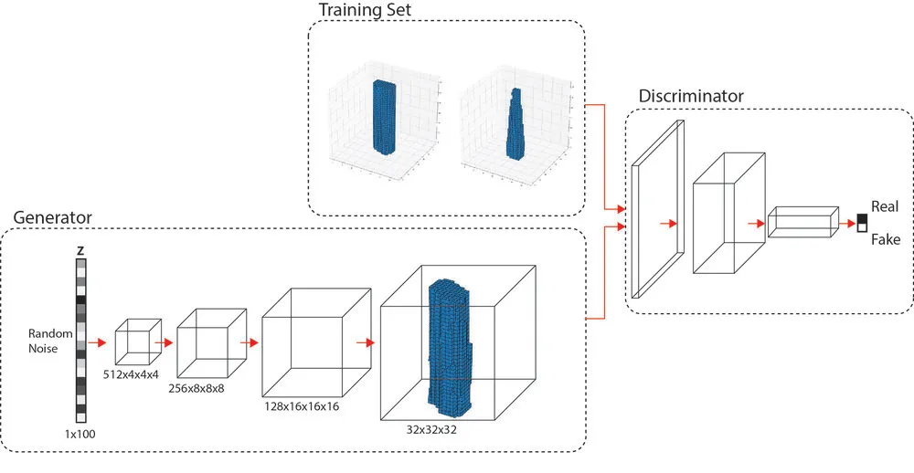
Deep networks have been used for various tasks around 3D object understanding and geometry generation. Li et al. [9], Su et al. [13], and Girdhar et al. [5] proposed to learn a joint embedding of 3D shapes and synthesized images for 3D object recognition. Using a recurrent network, Wu et al. [16], Xiang et al [18], and Choy et al. [3] attempted to reconstruct 3D objects from a wide selection of images. Other attempts at understanding 3D voxel based geometry representation was via exploring autoencoder based deep networks [5], [12]. Generative Adversial Networks (GAN) [6] introduces the use of a generator and an adversial discriminator, where the discriminator classifies real objects and objects created by the generator, while the generator attempts at confusing it. This in particular a is a favored framework for 3D object modeling as 3D object are highly structured, therefore the model is able to capture the structural difference of two 3 D objects [17]. Furthermore, 3D GAN could be used to sample through the probabilistic latent space creating a wide range of 3D dataset for design exploration and model training.
The biggest disadvantage of employing a 3D GAN to explore ideas is that the latent vector’s majority of dimensions are incomprehensible to a human designer. Furthermore, due to the enormous number of parameters, such a design space is difficult to explore. In this research, we aim to present a new, creative way of human-AI collaboration through the medium of AR, for the use-case of interior design - particularly, we focus on designing and placing furniture in a given space. To do this, we develop an AR based 3D drawing app, where users’ can use their phones to move in three dimensions and draw strokes that resemble a furniture of intent. The reason for using this mode of human-computer interaction is to allow users to move around their space, and conceptualise objects to-scale and in-position in their space through an easy-to-use AR drawing interface. Through interactive AR based 3D sketching, this project also aimed at creating a natural approach to interact with 3D GANs. We also present a novel algorithmic workflow for processing these sketches and represent them automatically, for use in a machine learning pipeline. We evaluate several machine learning algorithms to predict the mesh / mesh-representations and propose a Multi-Layer Perceptron (MLP) based regression method to reconstruct 3D meshes from user-input sketches through weightencoded neural implicit [4] prediction.
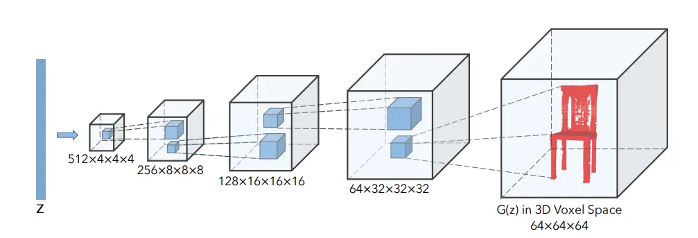
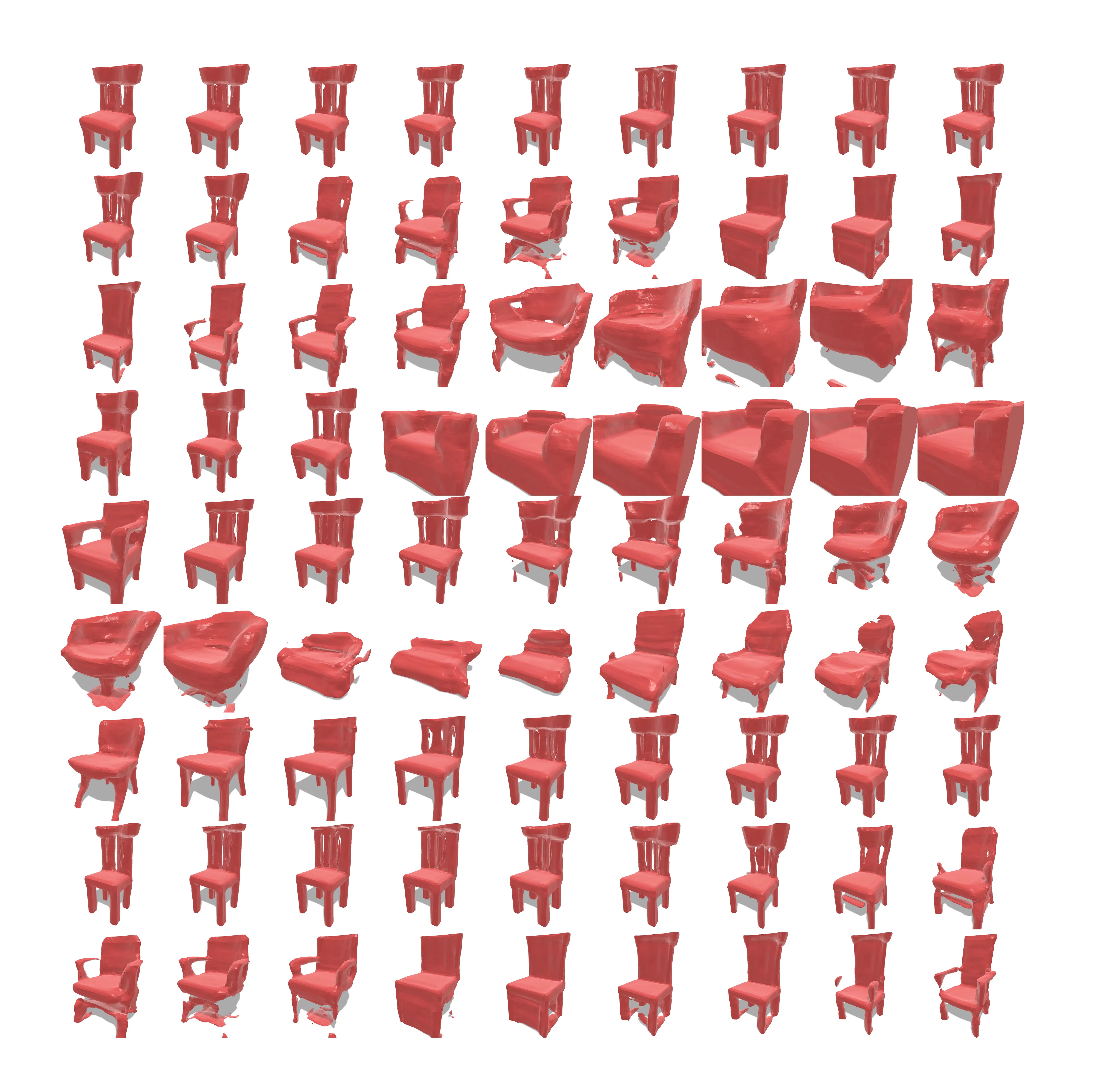
We begin preparing our data-set. For our proposed problem, we need a data-set that comprises of mesh-sketch pairs. There are several large-scale 3D object data-sets available like ShapeNET [2] that can be labeled with appropriate data. However - in our problem - we aim to predict meshes that are able to ”morph” themselves to different sizes and proportions of sketch strokes. So we would not only require perfect geometries, but also interpolations between several geometries to get hybridized results that work well with sketches of diverse shapes and sizes. Hence, we decide to generate our data artificially. To do this, we choose to use the pre-trained chair and sofa generators (Figure 1) from [17]. It presents a novel method to generate 3D objects with an architecture called 3D Generative Adversarial Network (3D-GAN), which uses recent breakthroughs in volumetric convolutional networks and generative adversarial nets to generate 3D objects from a probabilistic latent space.
Figure below: 3D GAN generator architecture
We first sample 1000 randomly generated 128-dimensional latent vectors that are distributed normally in the range [-2, 2]. We use these latent vectors and feed them into the 3D GAN to generate corresponding 3D meshes from the latent space of the generator. Each sampled latent vector corresponding to the generated mesh is stored in a csv file for later use. We also save the generated meshes as obj files. Some of the generated geometries are shown below.
Figure below: Generated 3D objects from 3D GAN latent space
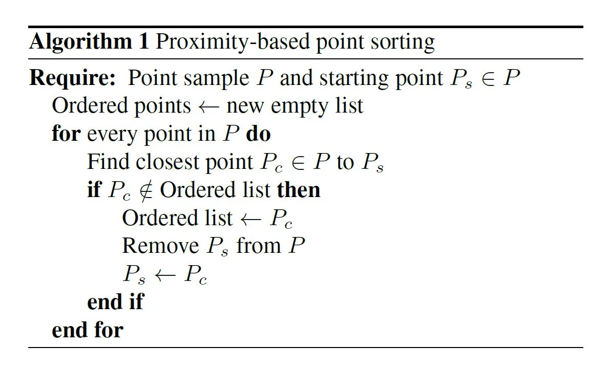
For our problem, there were no 3D sketch data-sets available. Hence, we design an algorithmic approach to generate our sketches from the mesh geometries sampled from the 3D GAN, in a parametric design tool called Grasshopper3D [11]. We aim to generate sketches that are natural looking and organic, that would look like a quick conceptual sketch - similar to what users would draw. In order to achieve such sketch strokes from our sampled meshes, the saved obj files of the meshes are loaded iteratively and several points are samples from the geometry. The number of sampled points is decided qualitatively based on how much they can represent the mesh morphology. In our case, 128 samples were identified to be sufficient. These sampled points are then sorted according to their spatial proximity in world coordinates. The sorting algorithm is shown below in the algorithm below.
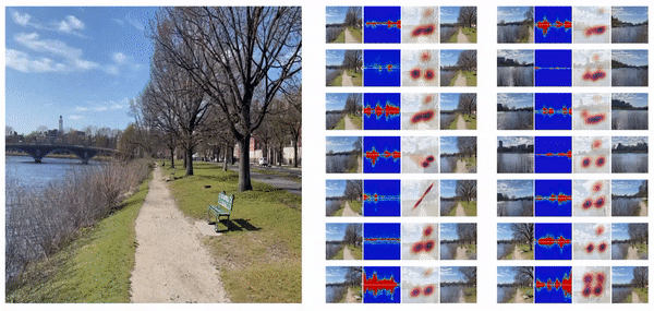
Once we have the sorted point-list, the points are joined by a polyline in order. This create a dense and jagged linelike curve along the sorted points. The polyline is then simplified and smoothed using B-spline approximation to a 3-degree curve. All the variables used in processing the line are parametric, and the final threshold values are calculated qualitatively for random samples from 3D GAN. The final smoothed curve resembles a conceptual sketch stroke, similar to what we were aiming. The overall process is illustrated in Figure 3. This process is repeated for all 1000 sampled meshes, and corresponding sketch strokes are recorded. Some of the generated sketches and their corresponding mesh samples are shown in the below figures.
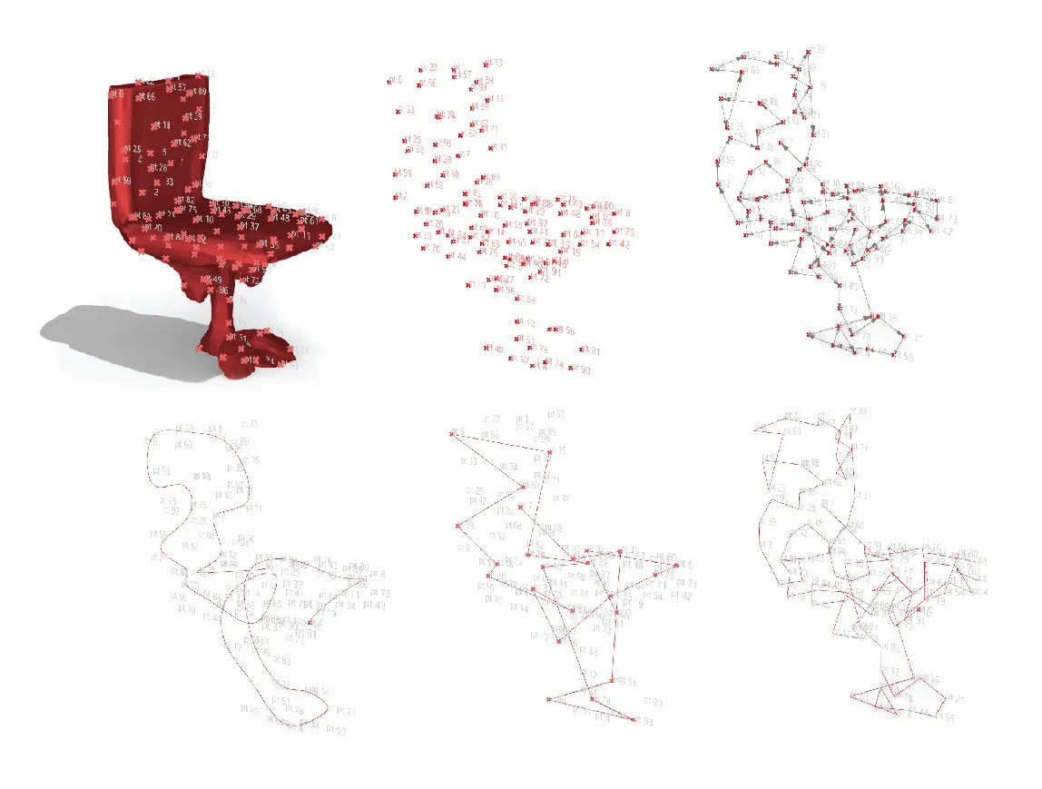
Algorithm to generate 3D sketch strokes from mesh. (clockwise) Sampling points on mesh, sampled points, sorting points based, polyline connecting sampled points, reduced polyline, B-spline smoothing to get sketch curve
Once we have the generated sketch strokes for the sample meshes, there needs to be a way to represent them. This representation is also required to process user-drawn sketches to use in a machine learning pipeline. We also want this representation to be proportional in dimension to the latent vectors that were used to sample different meshes from the 3D GAN. The latent vectors are 128 dimension vectors, and hence we initially decide the sketch representation vectors to be 128 dimensions as well. In order to do so, we sample 128 points from the generated sketch stroke of each mesh. Then, a bounding-box with a centroid is created around the sketch stroke, each of the sampled points from the previous step are connected from the bounding-box centroid. This creates a list of 128 vectors, each anchored at the centroid and connected to each corresponding point from the sampled points. These vectors are normalised to bounding box dimensions, to finally fall in the [0,1] domain. We then use this list of normalized vectors (taken in order of points) to represent our sketch vector. The overall process is illustrated in the below figures.
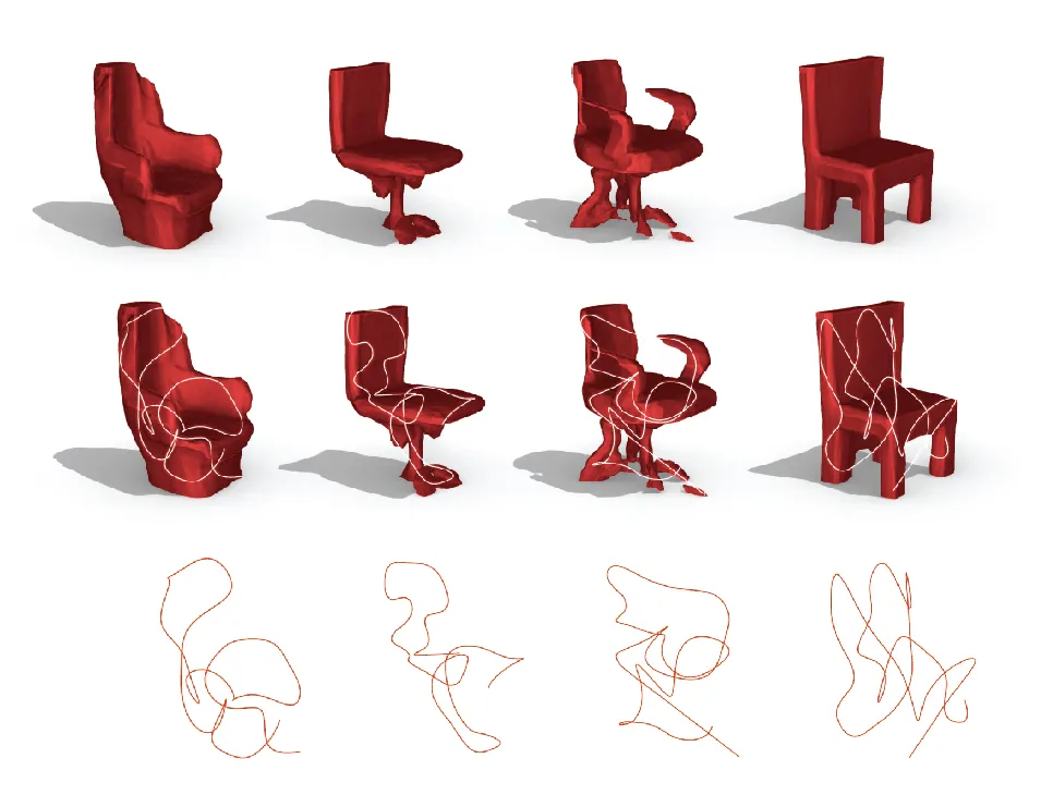
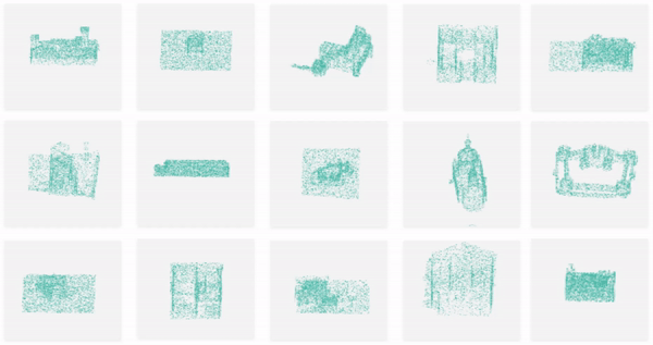
Examples of sampled meshes (above) and their generated sketch strokes (above).
Examples of sampled meshes (above) and their generated sketch strokes (above).
Our initial attempt to map sketches to meshes was to try to predict the latent vectors that were used to sample meshes - from the generated sketch representation vectors. We use a K-nearest neighbor (KNN) regression algorithm to try to achieve this. The intuition behind using KNN was to try to identify the latent vector that is closest to (in-terms of distance) the input sketch representation vector, and sample a mesh geometry from the 3D GAN with the predicted latent vector. KNN is also non-parametric to the given number of closest neighbors (K value), which means we won’t have the issue of average collapse - where we get a mean prediction across all input sketch representation vectors. We first run a hyper-parameter search using cross-validation, with the following parameter-space dictionary.
The result of the hyper-parameter search yielded 14 neighbors, ’distance’ weights - where each feature is weighed inversely proportional to their distance - and p value of 1 (Manhattan distance).
Overall training cycle for KNN regressor (below).
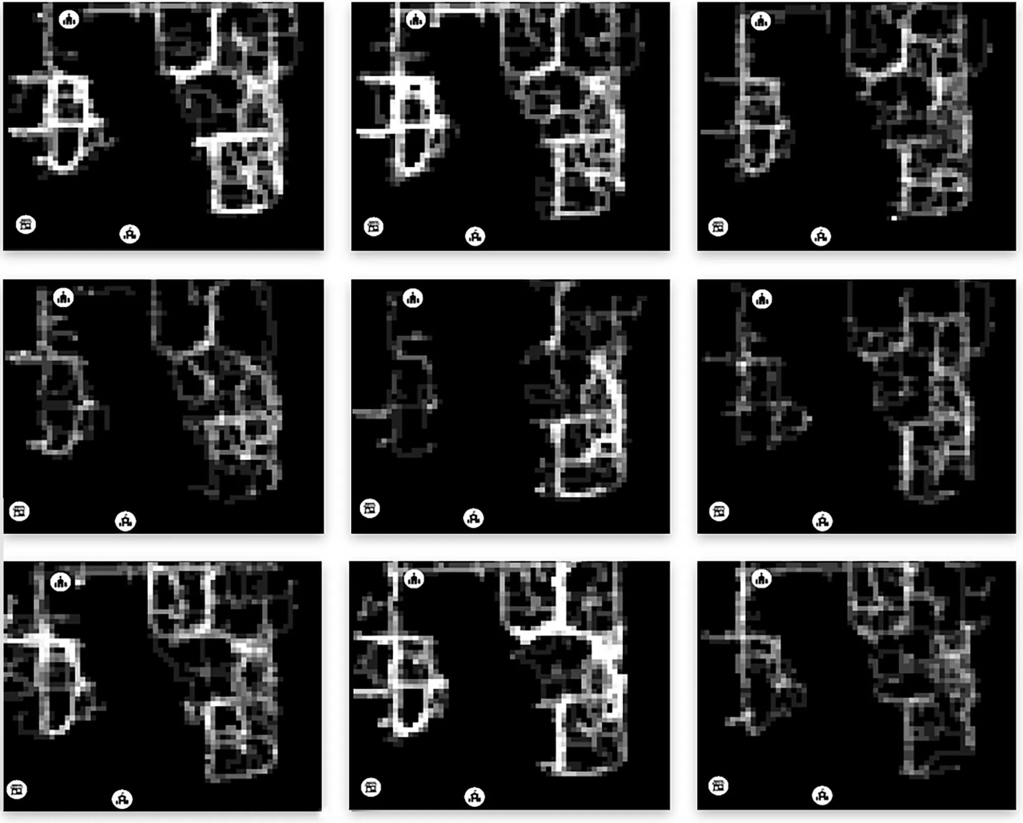
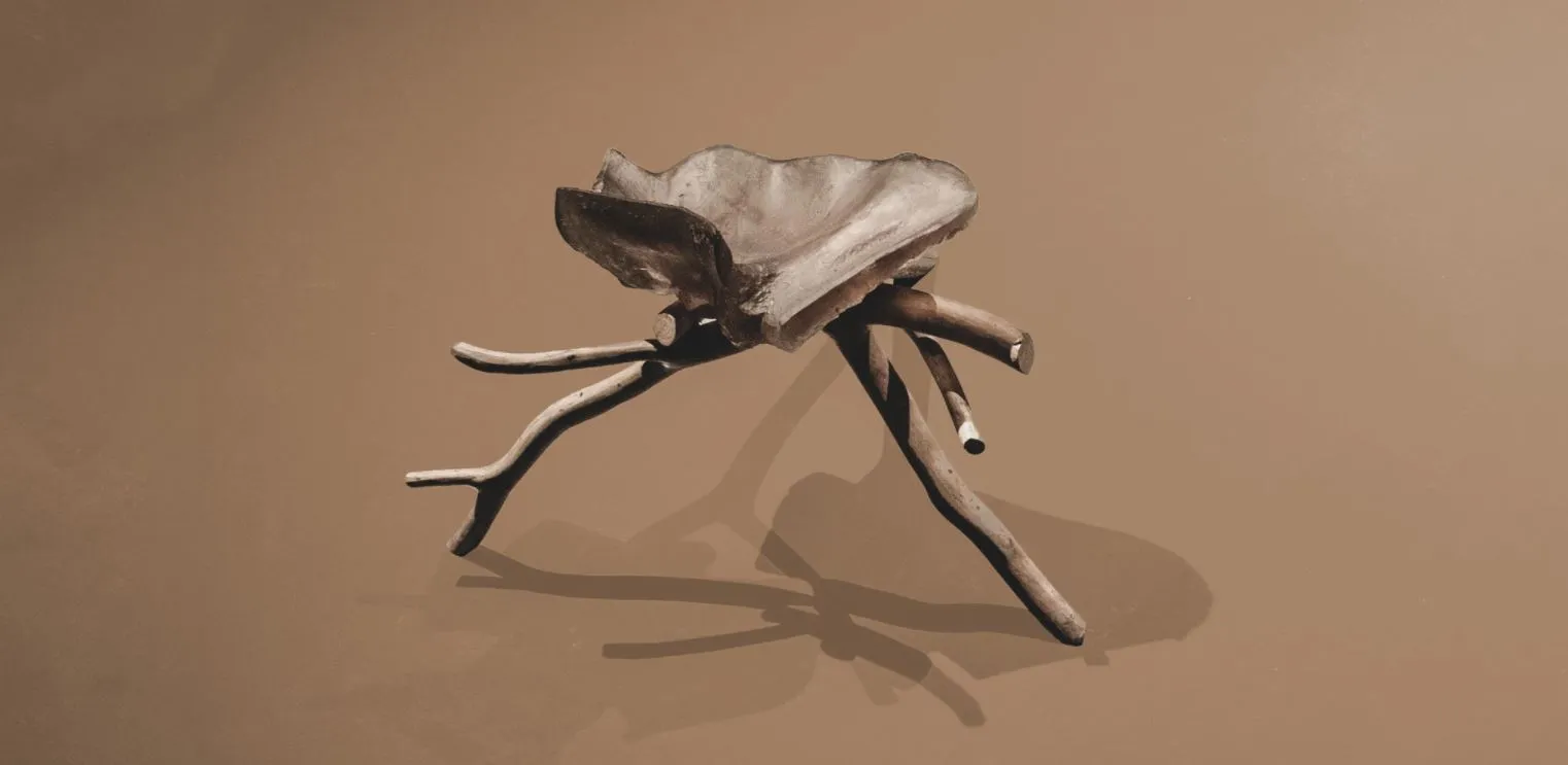
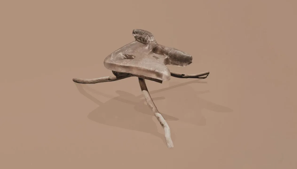
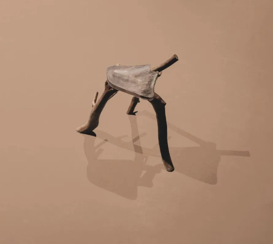
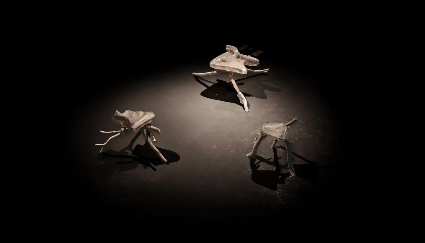
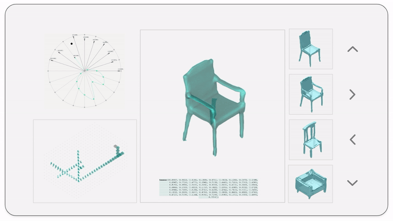
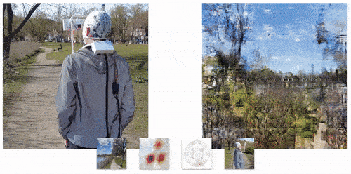
On using KNN Regression, we found that the model performed satisfactorily with a cross-validation accuracy of 71% (5 folds). These predictions were then fed back into the AR app, displaying the sampled mesh in the users’ environment. However, the results where very close to each other, predominantly predicting latent vectors that generated similar looking meshes. While the semantic features of the mesh - like hands, legs, shape - were well mapped, the overall shape, scale and proportions of the mesh did not match the input sketch. Some of the predictions in the AR app interface are shown below.
We noticed that the predicted meshes were semantically correct - where if the sketch indicates no hands, the mesh has no hands as well. However, they are either very similar in nature (1st, 2nd and 3rd images in Figure 7) or undesirable (4th image in Figure 7). We also noticed that for two very different latent vectors, the sampled meshes were very similar qualitatively. This suggested that rather than mapping sketches to latent vectors and sampling meshes, there needed to be a much more direct representation of the meshes. And consequently, we also need similar embeddings for the sketches for everything to work smoothly.
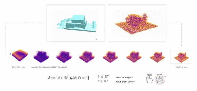
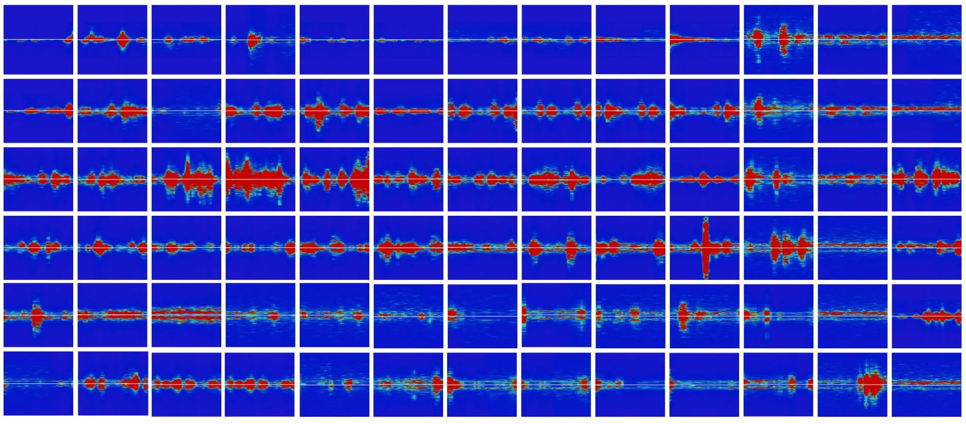
In our subsequent iteration, we represent the meshes and the sketches as neural implicits [4]. A Neural Implicit representation is a function that determines whether a queried point lies inside, outside or on the surface of our geometry. In this paper, we use Signed Distance Function (SDF) - that returns at any point, the distance to the outer surface of the geometry with the sign indicating whether the point is inside or outside. We recognize that it is easy to represent our meshes and the sketches using neural implicit functions. On training a model on these values, we can map between the sketch and mesh representations bidirectionally. We begin by sampling 100,000 points around the mesh and sketch objects independently, using Latin Hypercube Sampling. Then, we accept 10,000 samples from them based on their distance from the mesh/sketch. We do this to make sure that all our samples useful (i.e.) lie close to the object. The final samples and their corresponding distances are recorded as points and float respectively. This process is repeated iteratively for all 1000 mesh objects and sketch strokes, giving us four feature vectors :
The overall data representation process is illustrated in the diagram below. These vectors are then fed into a simple MLP regression in different combinations and evaluated. First, we train pairs of sketchSamples and meshDistances to be able to predict implicit mesh representation, given the sketch samples. If we get the meshDistances, we can reconstruct the mesh using algorithms like cube-marching. In our next iteration, we train using pairs of sketchDistances and meshDistances. The intuition behind this experiment was to be able to predict meshDistances from sketchDistances. And then finally, we train the model with pairs of sketchSamples and meshSamples to be able to map directly between the two samples of points. These experiments are further explained in the next section.
Above: Accepted points from Latin Hypercube sampling around meshes and sketches with decreasing distance visibility. We felt that at the 10,000 sample mark, the points were spread well around both the sketch and the mesh.
The model is a simple MLP Regressor, with 8 hidden layers of 512 dimensions each as shown in Figure 8. We use ReLU activation and Adam Optimizer with a learning rate of 0.0001. The model is trained for 200 epochs with a batch-size of 50 samples. We use L1 Loss for training.
The training data used for the model is as follows:
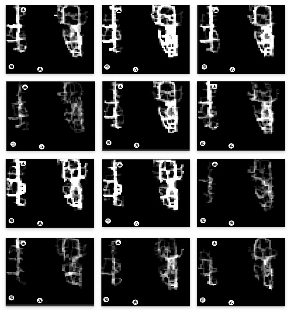
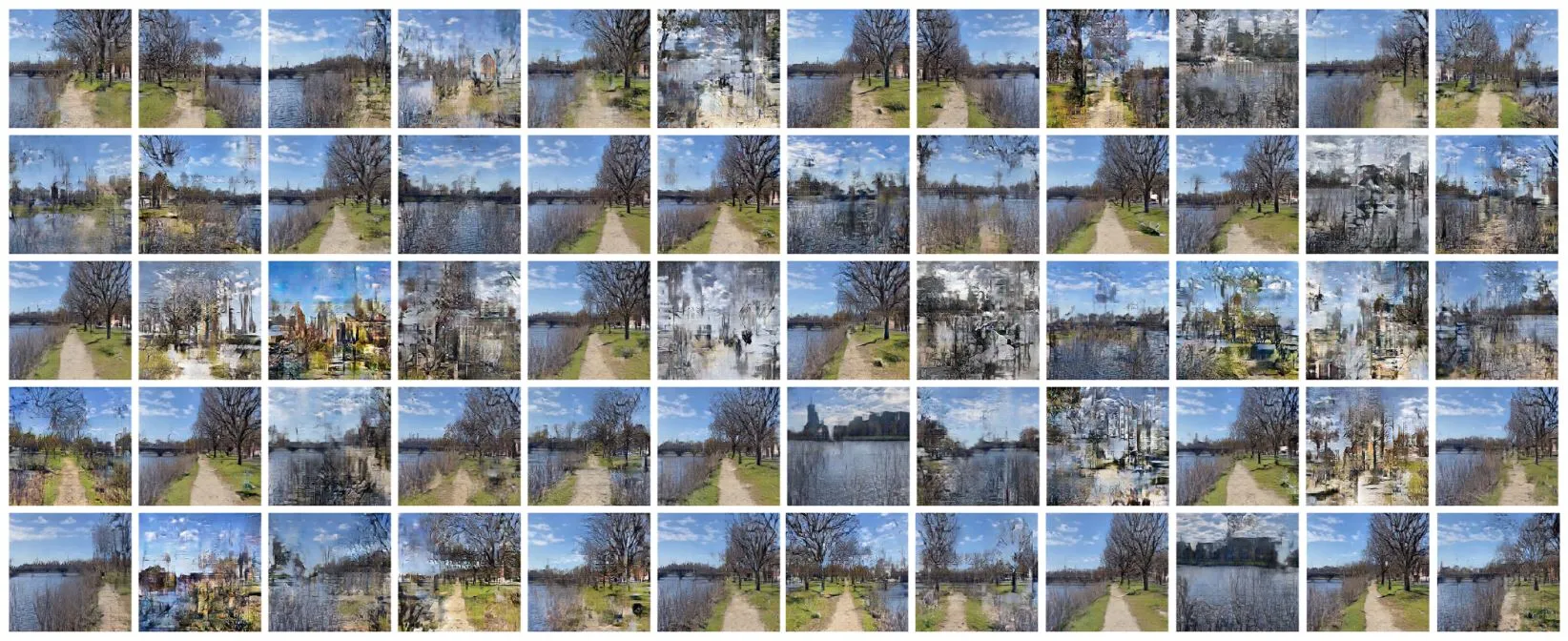
Here the goal was to predict meshDistances on the sketch sample points in order to get a SDF of the mesh for reconstruction. So, when a user draws a sketch, we can sample points around the sketch and get a SDF of the mesh on those samples from the MLP. The results were really interesting, with more diversity in predictions. Along with semantic features like arms or legs, even the scale and proportions are matched to a great extent. Training loss is shown below.
The objective of this experiment was to be able to predict a SDF of the mesh from the sketchDistances for reconstruction. This is to accommodate multiple strokes drawn by the user. If the user draws a new stroke on an existing stroke, instead of sampling points again, we can recalculate the distances and directly get the mesh SDF for reconstruction. The results were qualitatively good, similar to the previous experiment. Training loss is shown below.

The intuition behind this final experiment was to see if point-to-point regression would yield better results. On training with sketchSamples and meshSamples, the results were fairly similar to the previous two examples. All experiment predictions are shown below.
While the KNN regression performed satisfactorily in predicting latent vectors for input sketch-vectors, the MLP regression with SDF based neural implicit representation worked best for the current problem. Through this paper, we aim to create a robust, modular and easy to use AR application that translates mid-air drawn 3D sketches into mesh geometries using an MLP based regression model. The front-end interface provides various controls and tools that aid in the drawing processes and the visualization of the 3D geometries. Simple 3D gestural sketches suffice for an accurate prediction. Therefore, allowing users with minimal drawing skill-set to equally use the tool and prototype.
[1] Fologram.com. In https://fologram.com.
[2] Angel X Chang, Thomas Funkhouser, Leonidas Guibas, Pat Hanrahan, Qixing Huang, Zimo Li, Silvio Savarese, Manolis Savva, Shuran Song, Hao Su, et al. Shapenet: An information-rich 3d model repository. arXiv preprint arXiv:1512.03012, 2015.
[3] Christopher B Choy, Danfei Xu, JunYoung Gwak, Kevin Chen, and Silvio Savarese. 3d-r2n2: A unified approach for single and multi-view 3d object reconstruction. In European conference on computer vision, pages 628–644. Springer, 2016.
[4] Thomas Davies, Derek Nowrouzezahrai, and Alec Jacobson. On the effectiveness of weight-encoded neural implicit 3d shapes. arXiv preprint arXiv:2009.09808, 2020. 2
[5] Rohit Girdhar, David F Fouhey, Mikel Rodriguez, and Abhinav Gupta. Learning a predictable and generative vector representation for objects. In European Conference on Computer Vision, pages 484–499. Springer, 2016.
[6] Ian Goodfellow, Jean Pouget-Abadie, Mehdi Mirza, Bing Xu, DavidWarde-Farley, Sherjil Ozair, Aaron Courville, and Yoshua Bengio. Generative adversarial nets. Advances in neural information processing systems, 27, 2014.
[7] Kin Chung Kwan and Hongbo Fu. Mobi3dsketch: 3d sketching in mobile ar. In Proceedings of the 2019 CHI Conference on Human Factors in Computing Systems, pages 1–11, 2019.
[8] Mingyang Li and Anastasios I Mourikis. High-precision, consistent ekf-based visual-inertial odometry. The International Journal of Robotics Research, 32(6):690–711, 2013.
[9] Yangyan Li, Hao Su, Charles Ruizhongtai Qi, Noa Fish, Daniel Cohen-Or, and Leonidas J Guibas. Joint embeddings of shapes and images via cnn image purification. ACM transactions on graphics (TOG), 34(6):1–12, 2015.
[10] Esha Nerurkar, Simon Lynen, and Sheng Zhao. System and method for concurrent odometry and mapping, Oct. 13 2020. US Patent 10,802,147.
[11] David Rutten, Robert McNeel, et al. Grasshopper3d. Robert McNeel & Associates: Seattle, WA, USA, 2007.
[12] Abhishek Sharma, Oliver Grau, andMario Fritz. Vconv-dae: Deep volumetric shape learning without object labels. In European Conference on Computer Vision, pages 236–250. Springer, 2016.
[13] Hao Su, Charles R Qi, Yangyan Li, and Leonidas J Guibas. Render for cnn: Viewpoint estimation in images using cnns trained with rendered 3d model views. In Proceedings of the IEEE international conference on computer vision, pages 2686–2694, 2015.
[14] Dakuo Wang, Elizabeth Churchill, Pattie Maes, Xiangmin Fan, Ben Shneiderman, Yuanchun Shi, and Qianying Wang. From human-human collaboration to human-ai collaboration: Designing ai systems that can work together with people. In Extended abstracts of the 2020 CHI conference on human factors in computing systems, pages 1–6, 2020.
[15] H. James Wilson and Paul R. Daugherty. Collaborative intelligence: Humans and ai are joining forces. In Harvard Business Review.
[16] Jiajun Wu, Tianfan Xue, Joseph J Lim, Yuandong Tian, Joshua B Tenenbaum, Antonio Torralba, and William T Freeman. Single image 3d interpreter network. In European Conference on Computer Vision, pages 365–382. Springer, 2016.
[17] JiajunWu, Chengkai Zhang, Tianfan Xue, Bill Freeman, and Josh Tenenbaum. Learning a probabilistic latent space of object shapes via 3d generative-adversarial modeling. Advances in neural information processing systems, 29, 2016.
[18] Yu Xiang,Wongun Choi, Yuanqing Lin, and Silvio Savarese. Data-driven 3d voxel patterns for object category recognition. In Proceedings of the IEEE conference on computer vision and pattern recognition, pages 1903–1911, 2015.
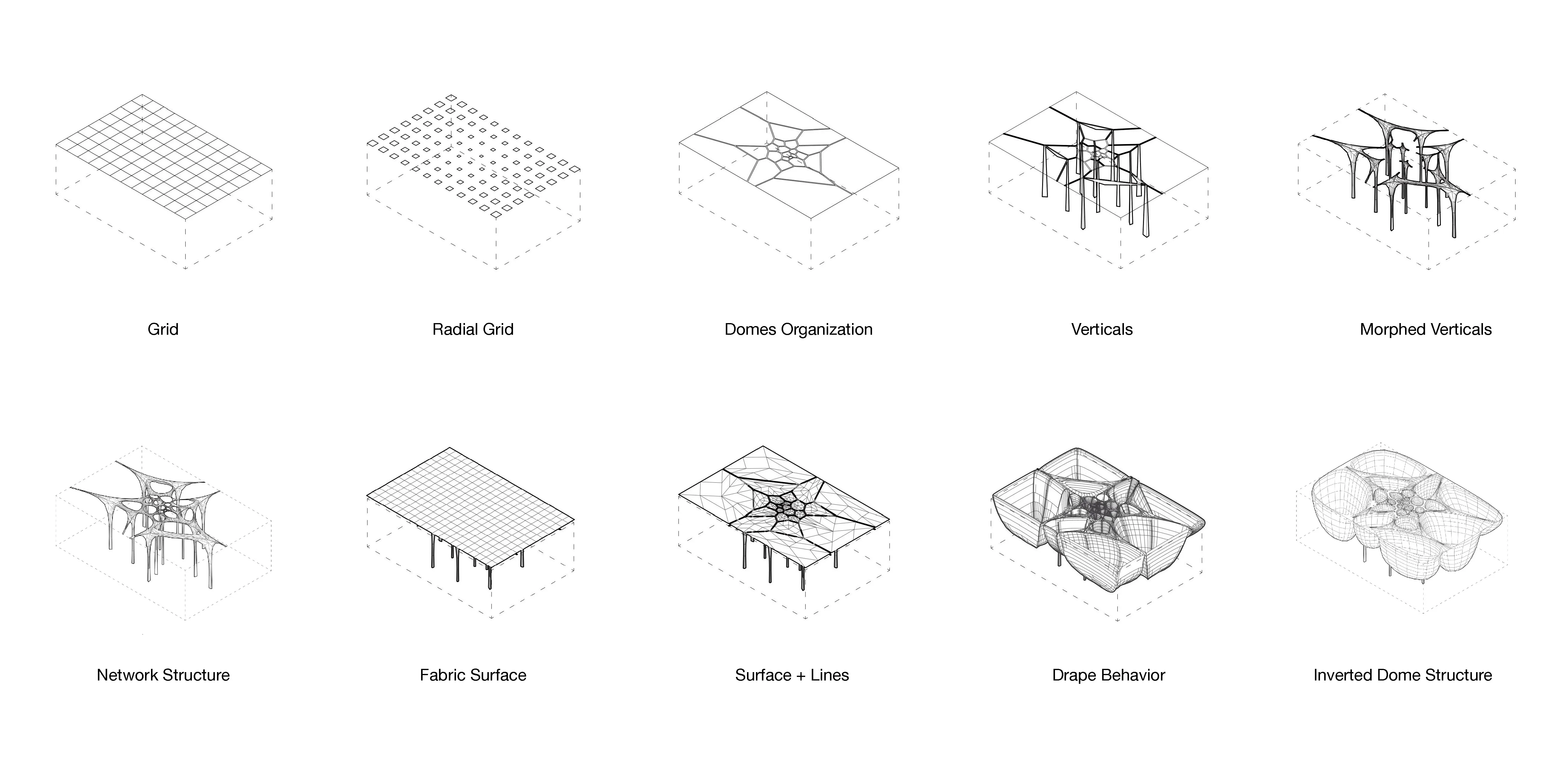
Figure-ground building to site diagrams and assembly massing diagrams
Designing the processional experient, pragmmatic layout, and relation to site / connectivities.
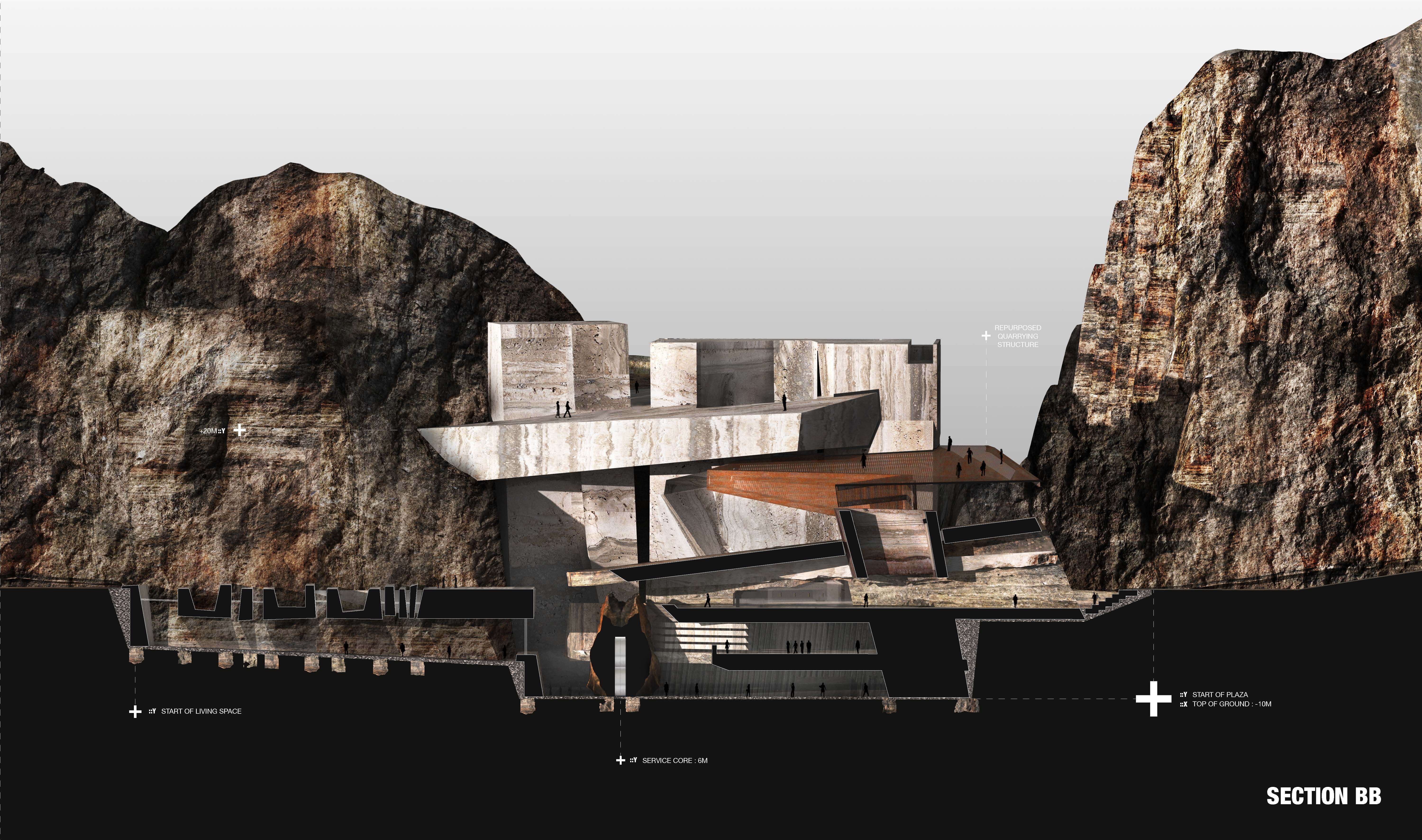
The project centers on exploring the relationship between site, landscape and building in-relation with time. The design process required the negotiation and resolution of the tensions between material massing, programmatic organizational forms and architectural systems to respond to the subject of inquiry: an art campus.
The arm projects forward to act as a support based or scaffolding for the rock above. This arm is gently pulled out after the rock ontop is stabilized by another rock on top of it.
Shifting continously between the screen and the lab, the processes enabled physical material prototyping to be a core part of the design decisions.
Sectionally Trapped Objects
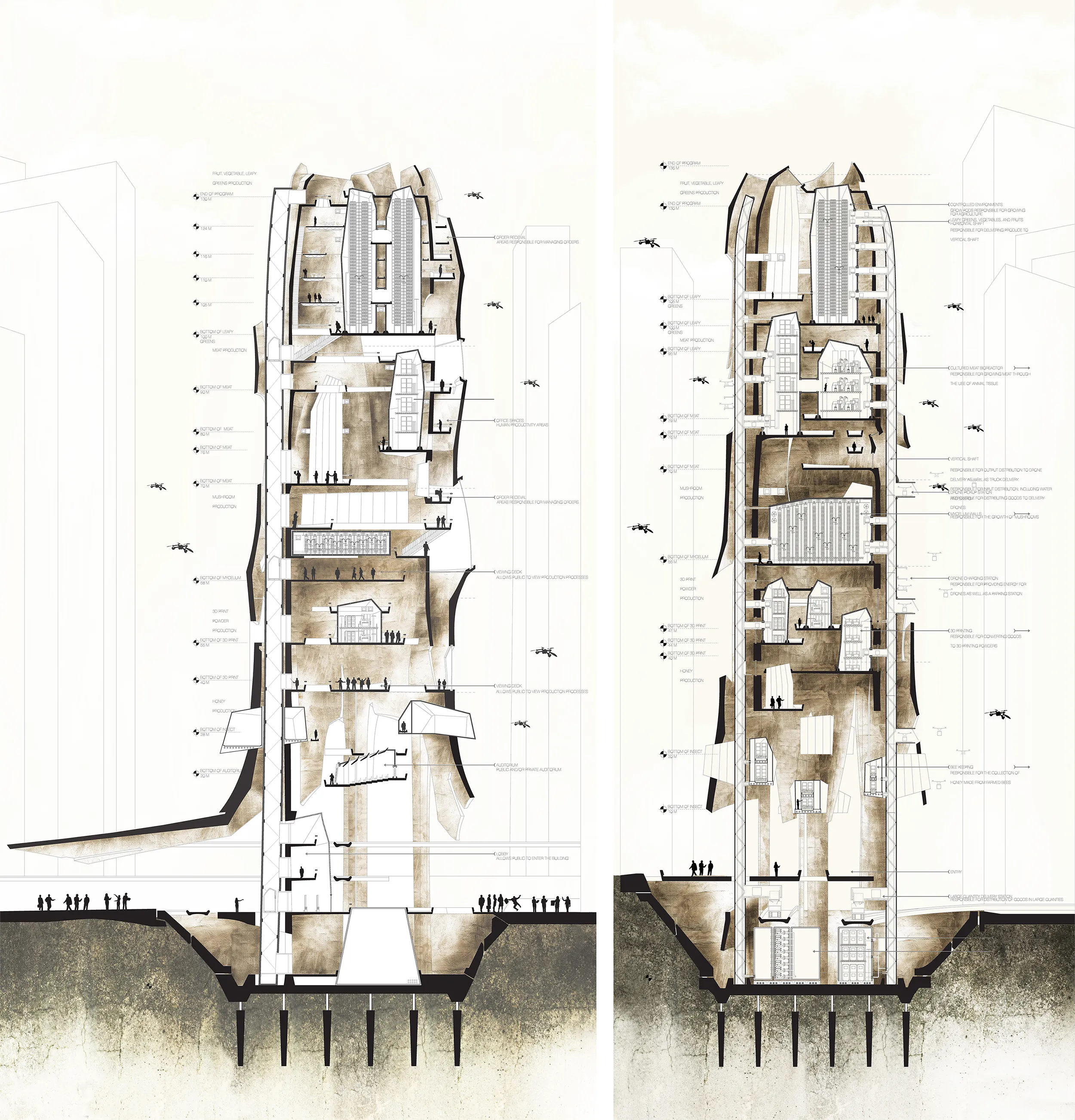
The diagrams below indicate the sub-programs the farm houses: Collection center, 3D printing powder factory, Bee farms, Mycelium grown coffee and mushroom spaces, green farming and lab grown meat. The factory is able to grow proportionally to the density of the neighborhood the farm is located in.
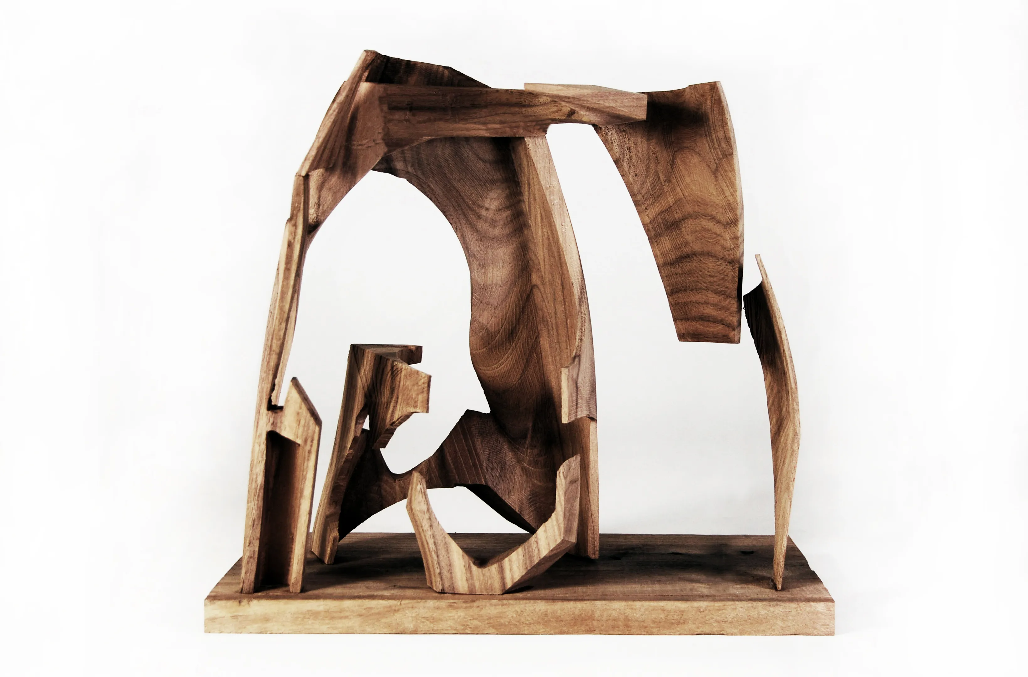
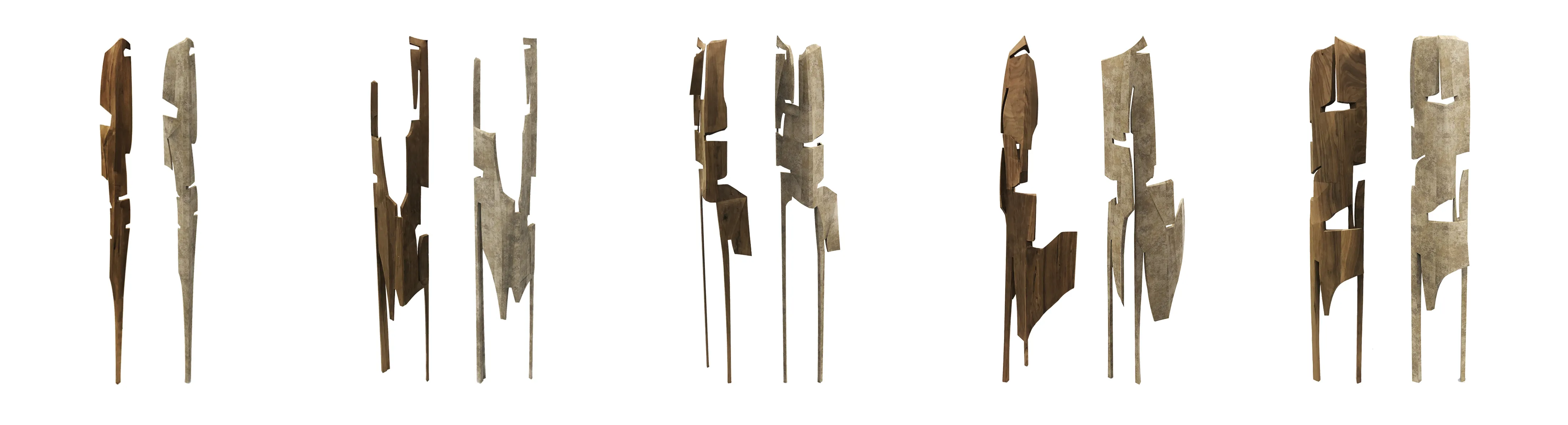
Formally we explored abstract gestural and figural relationships of a shell structure to house sectionally trapped volumes. The shell tares, splits and folds to correspond to programmatic and pragmatic needs. The shell thickens and hybridize with a denser cluster of columns for structural requirements.
The project uses physical models as a tool to explore structural and organizational systems of the tower to house various programs: Bee farm, hydroponics, mycelium grown beans and mushroom, composting stations, water storage tank, 3d printing sugars and lab grown meat.
The program multiplies differently for different sites to understand the scale the tower could serve for in different locations.
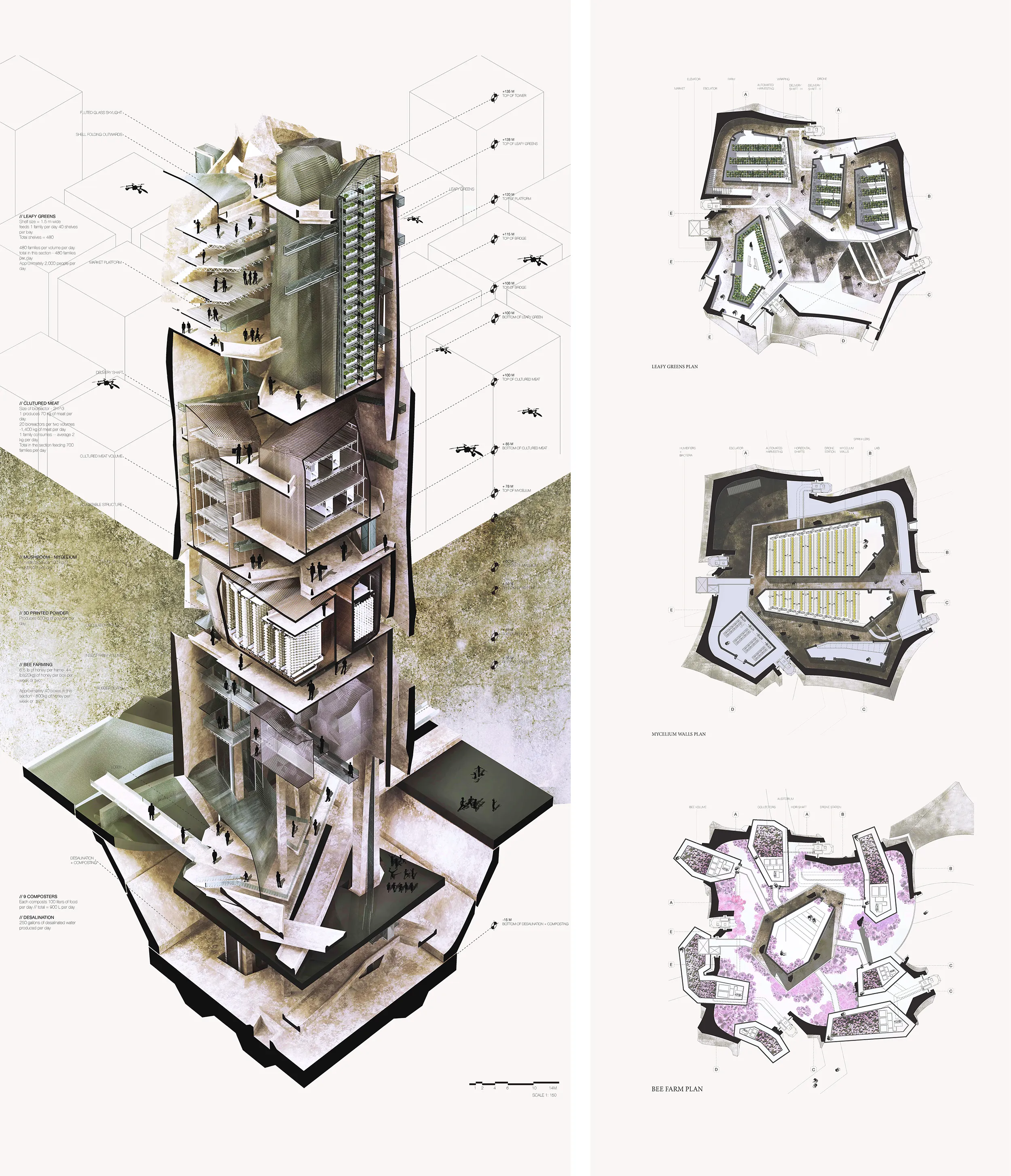
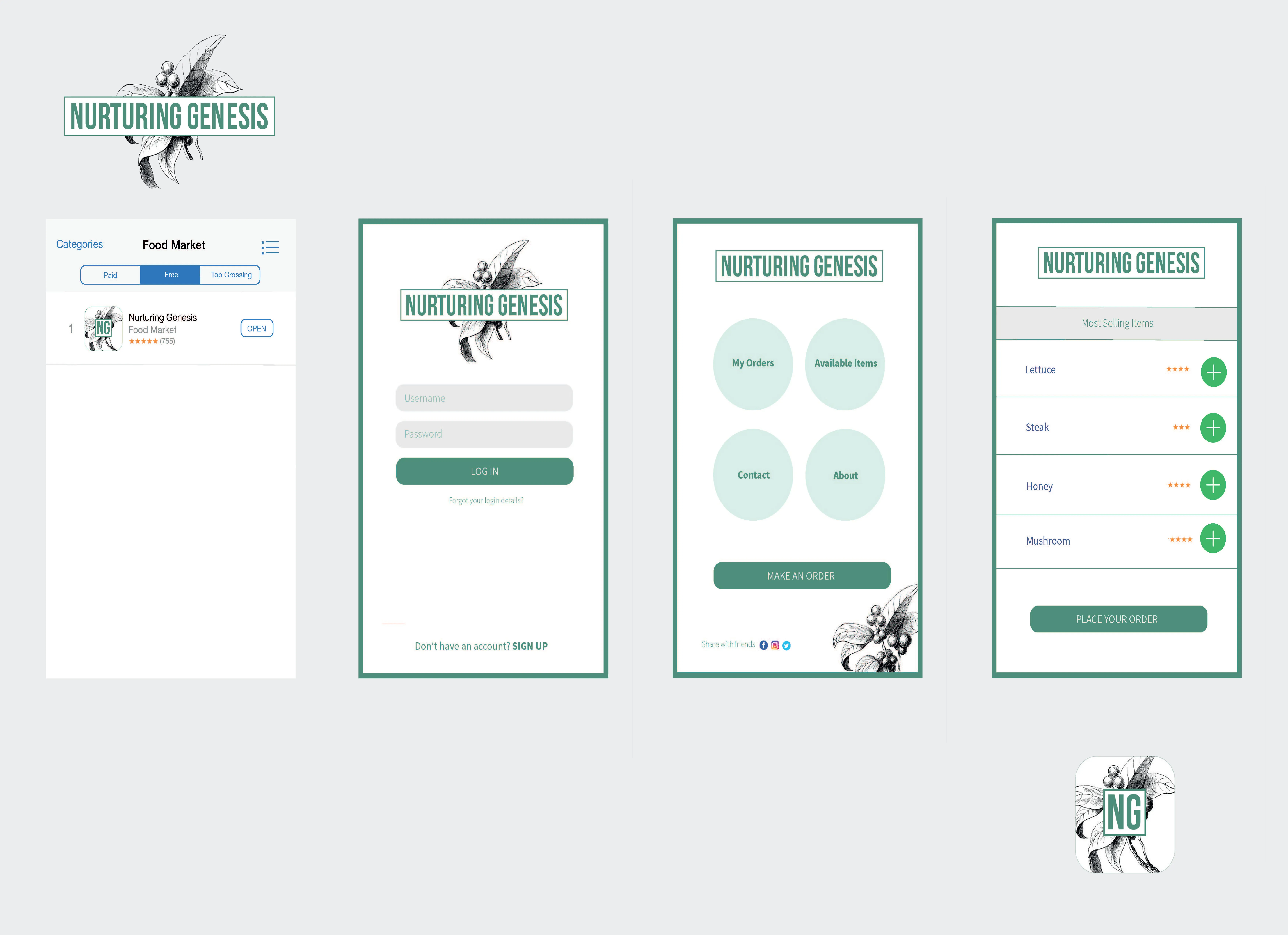
An application interface is develop to simulate the ordering and delivery process.
Digital design to fabrication precision using 3-axis CNC router to mill segments of each shell that are then assembled manually.
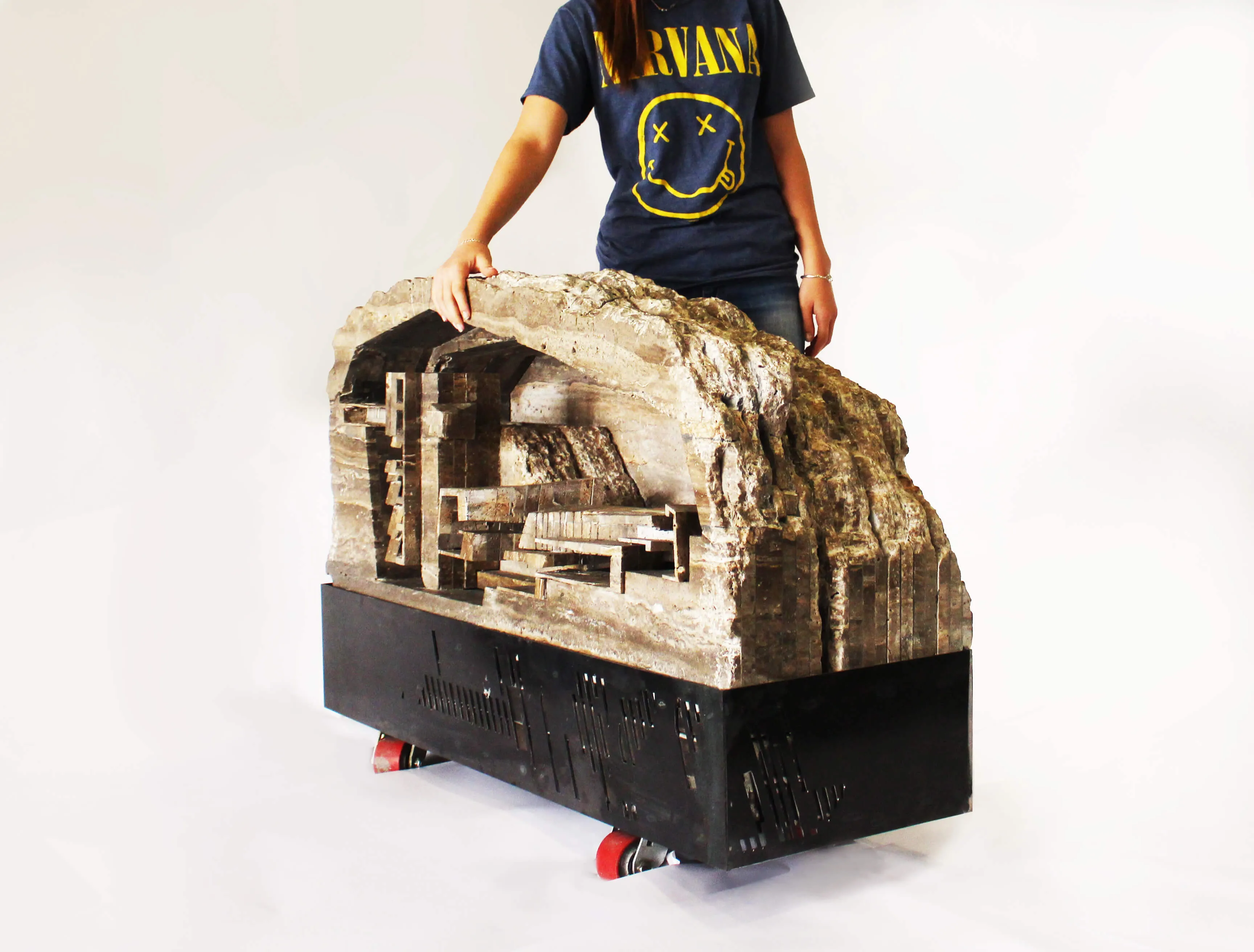
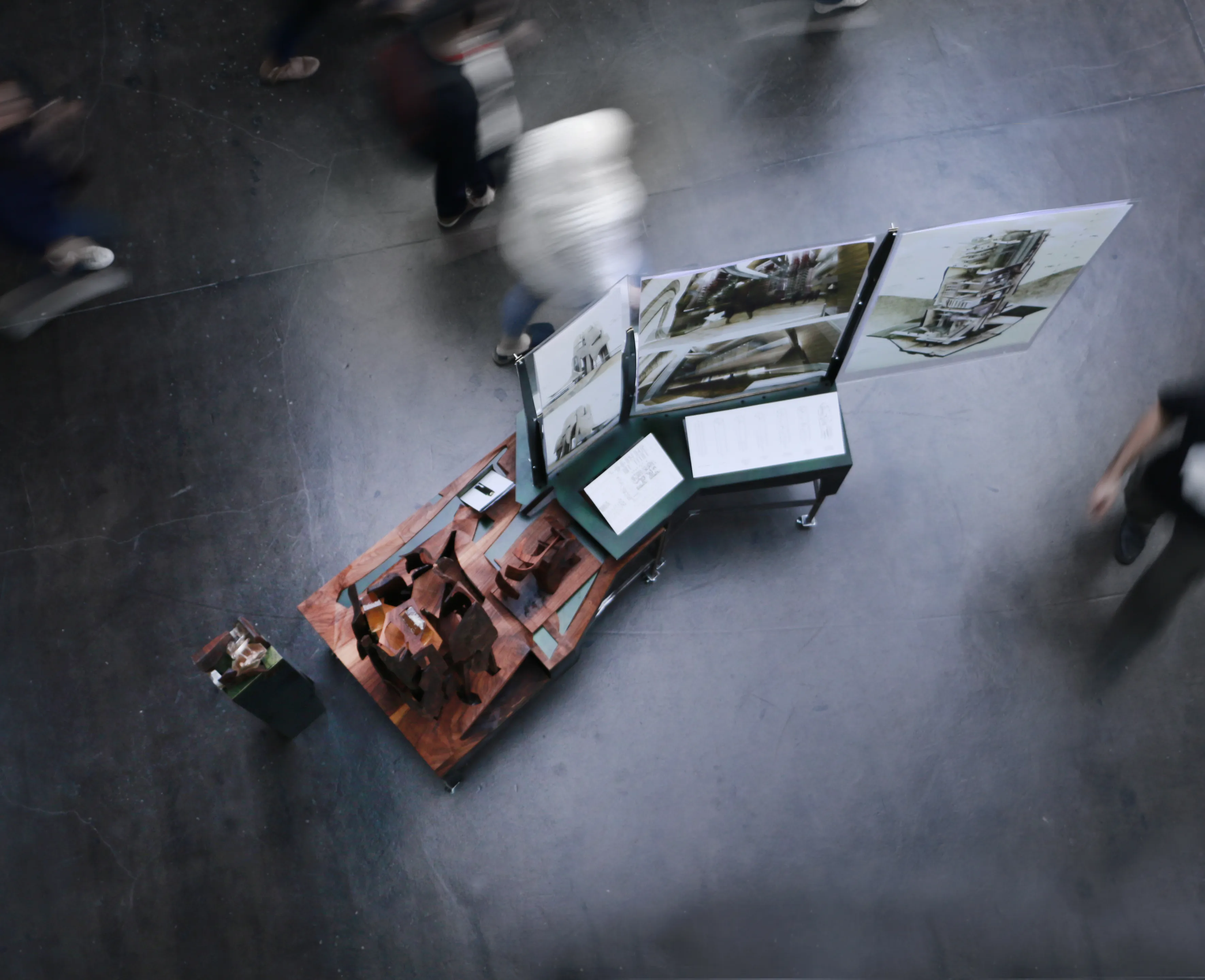
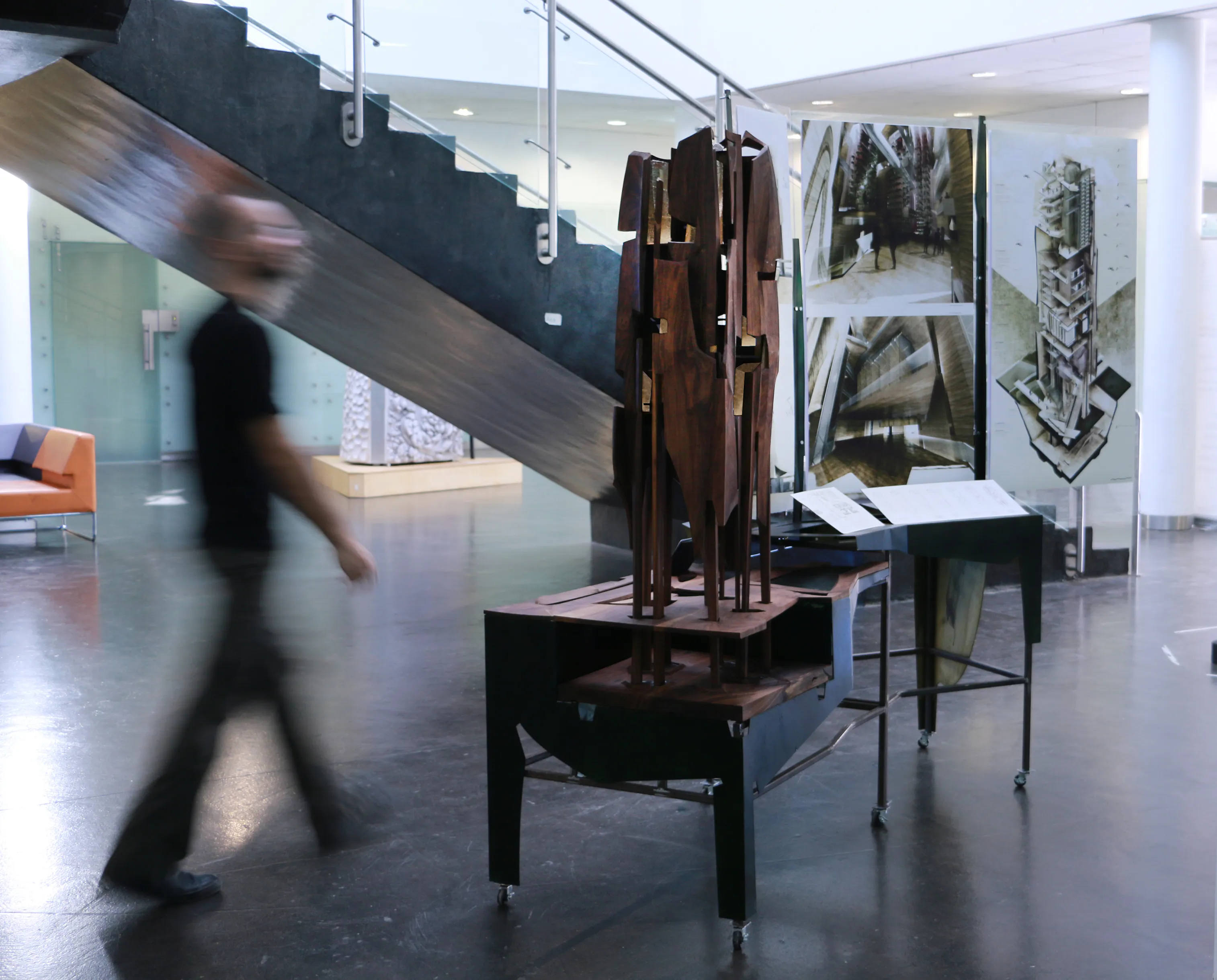
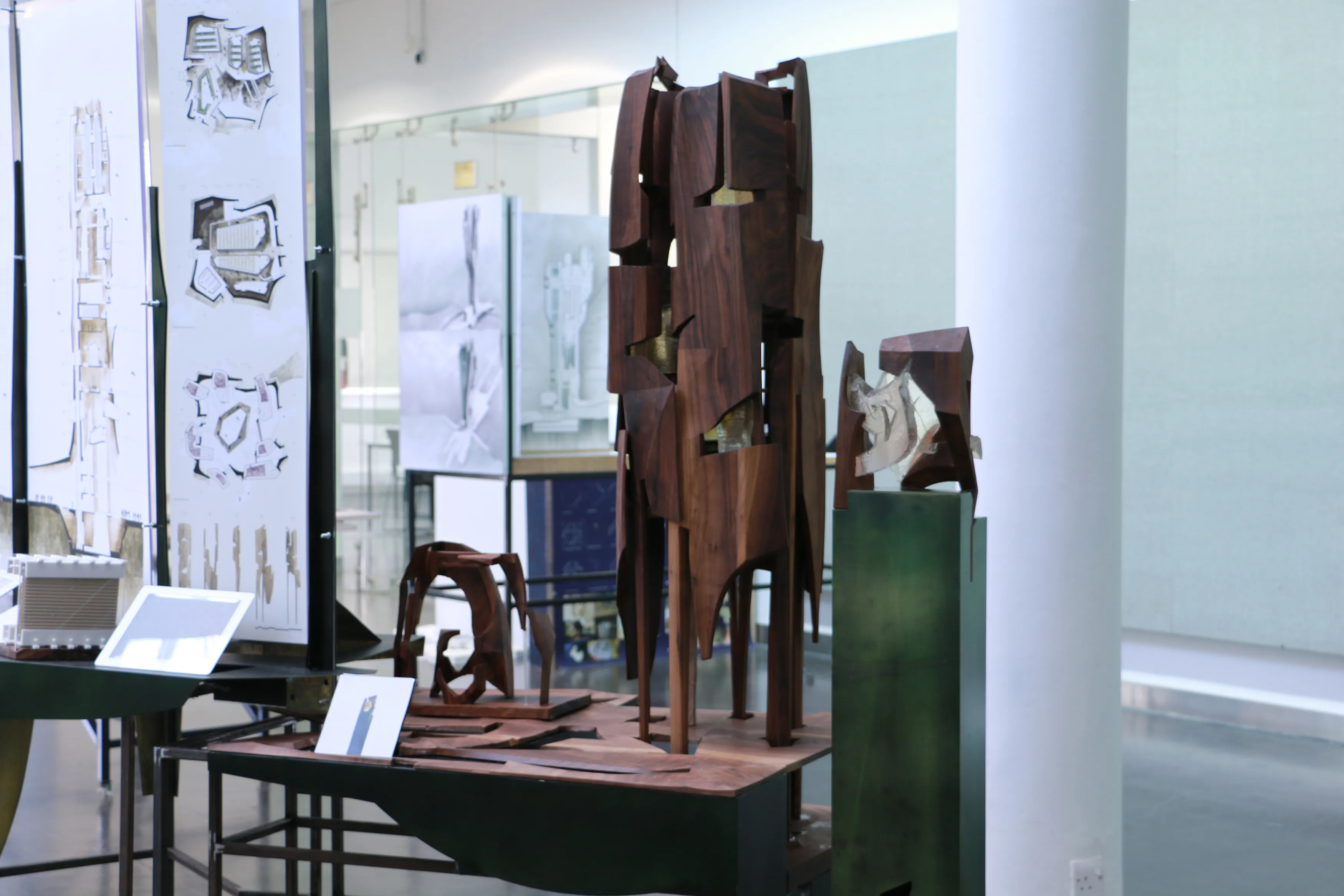
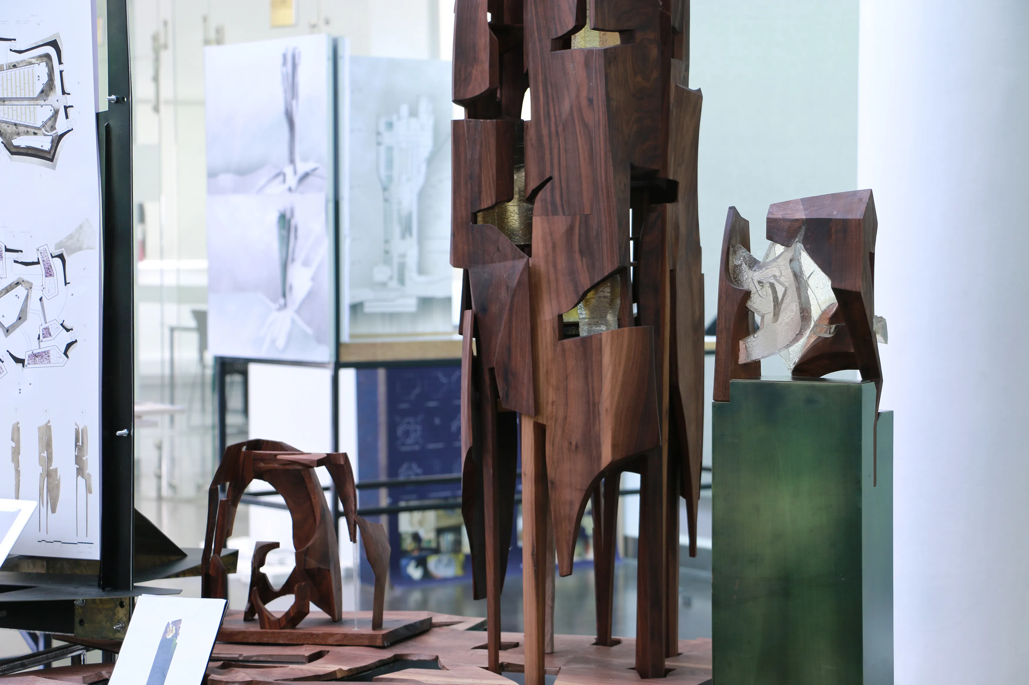
The project in display in an integrative base the combined the physical models, the project drawings, catalogues, and informatics.
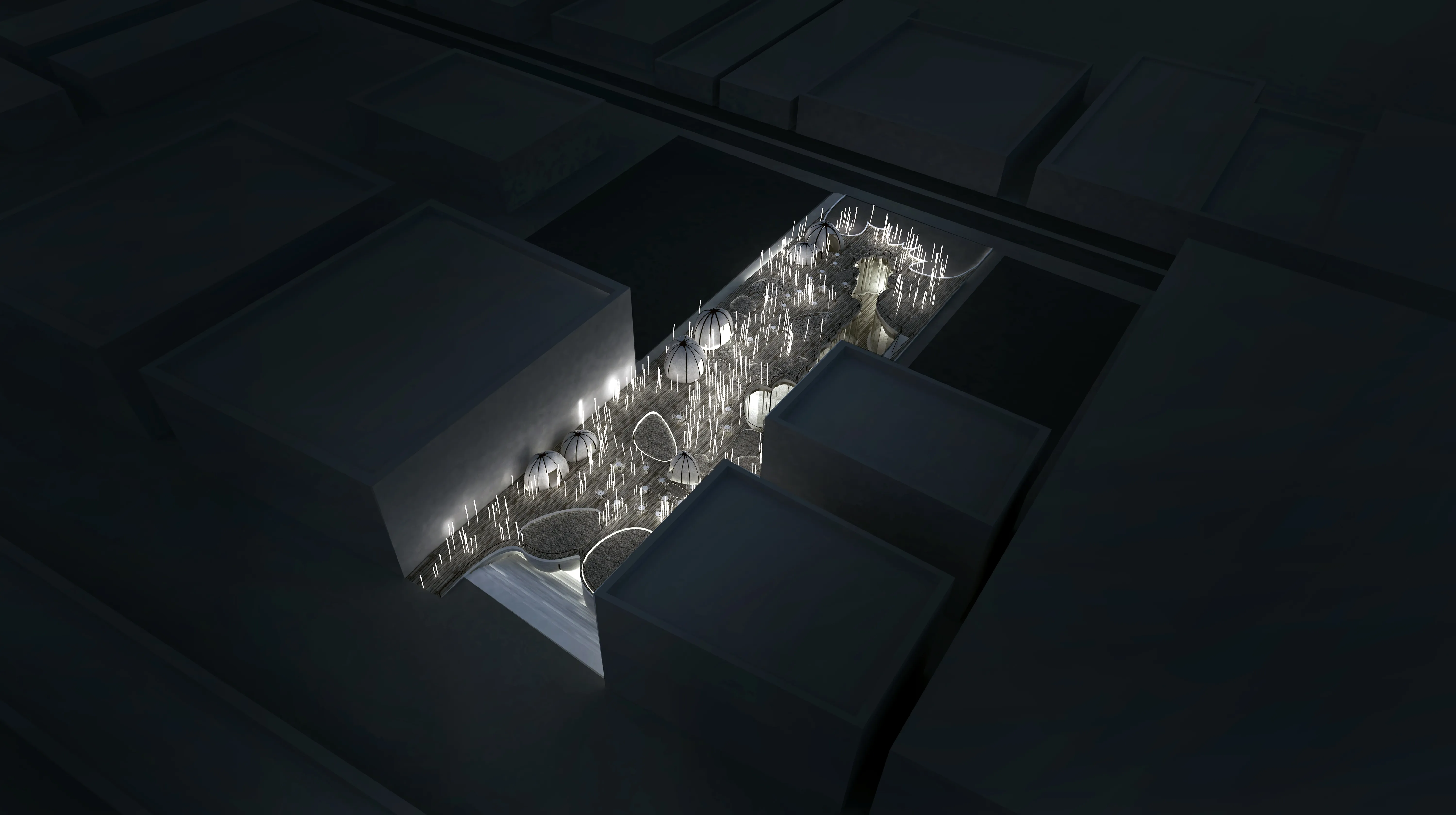
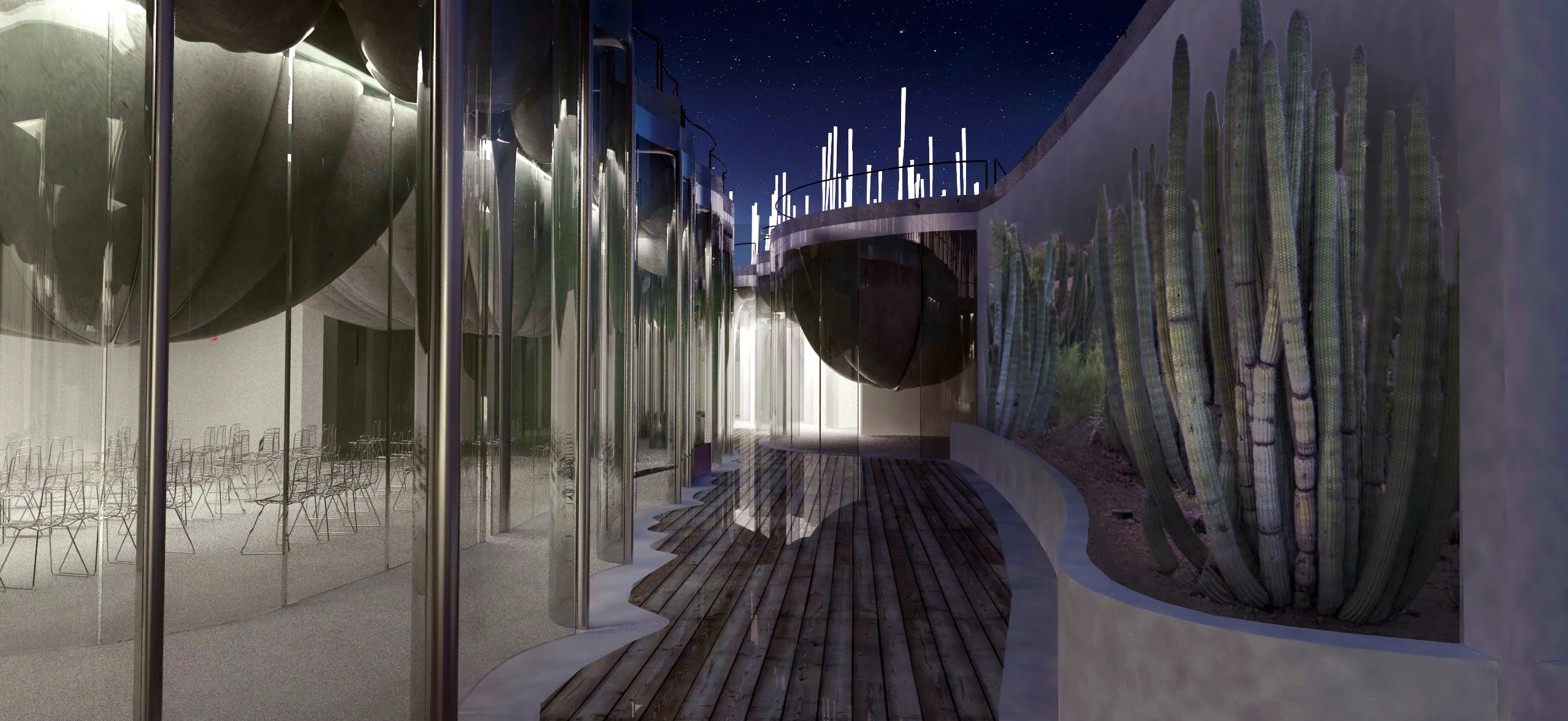
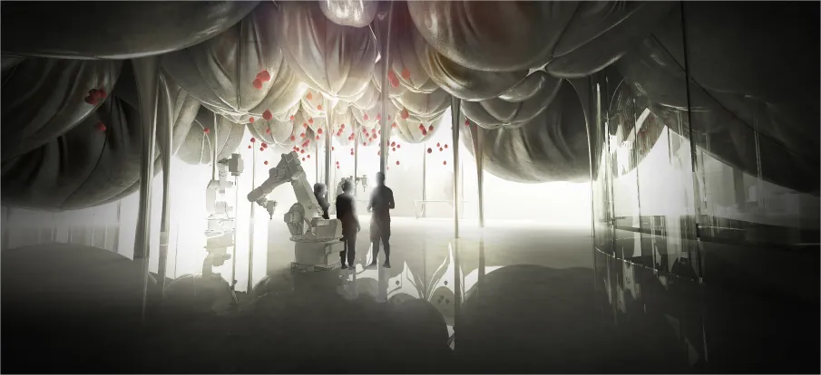
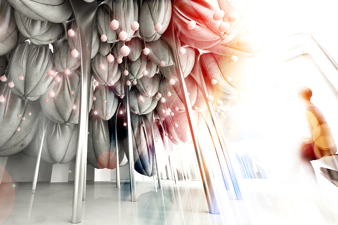
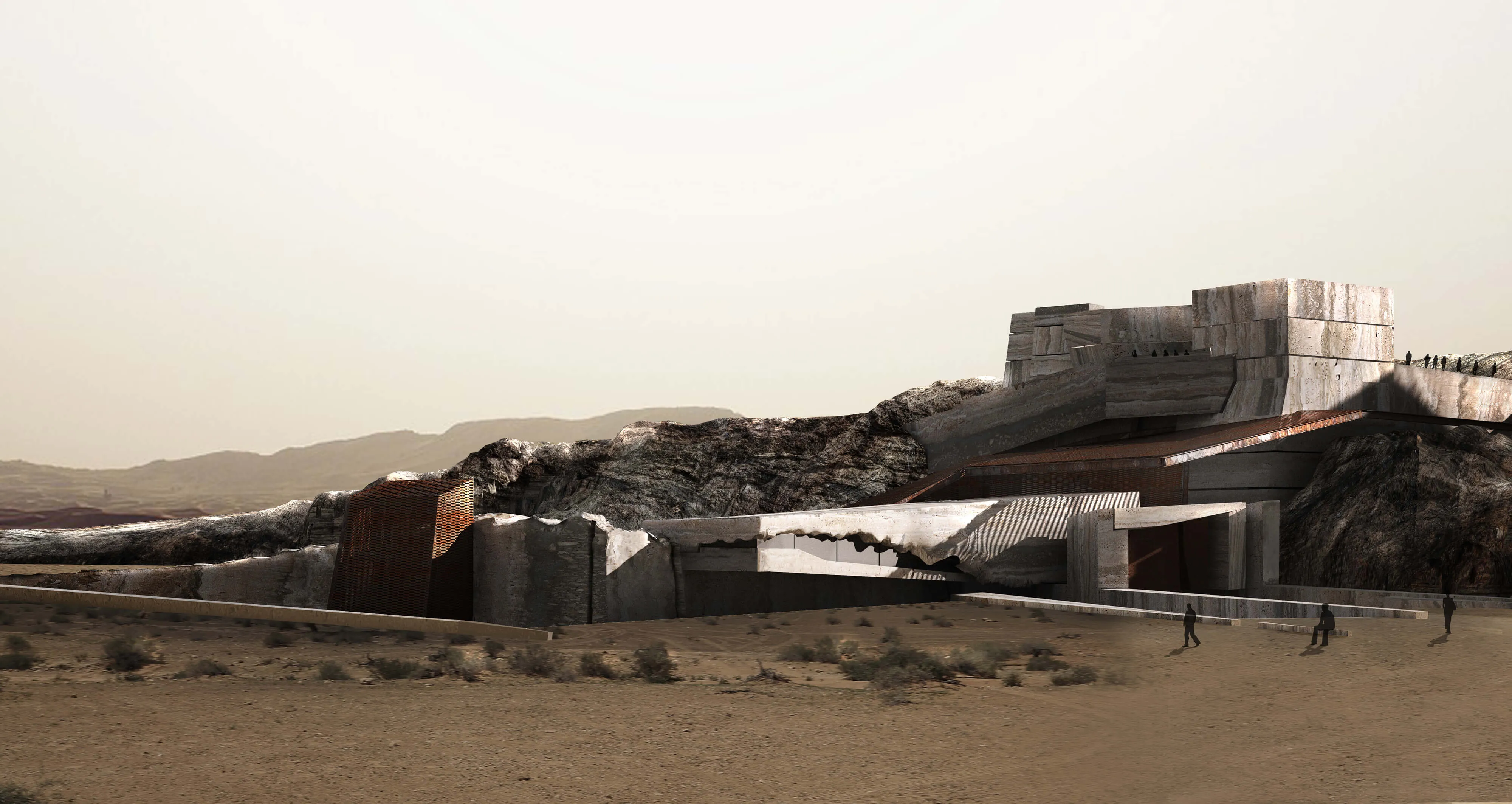
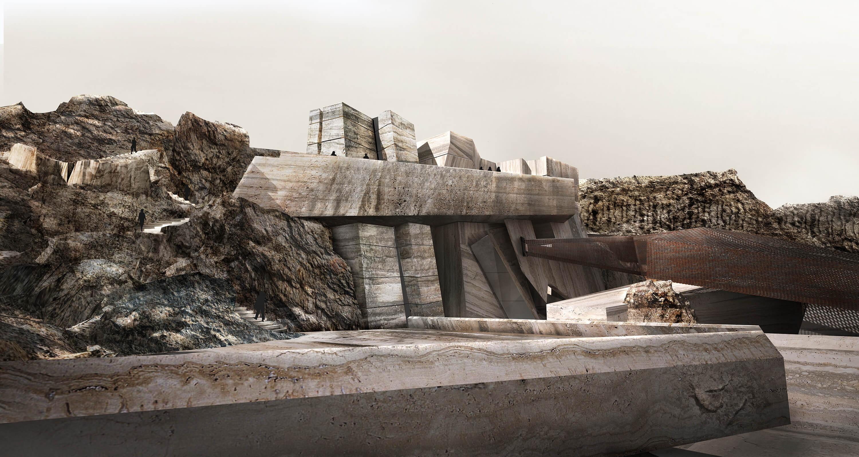
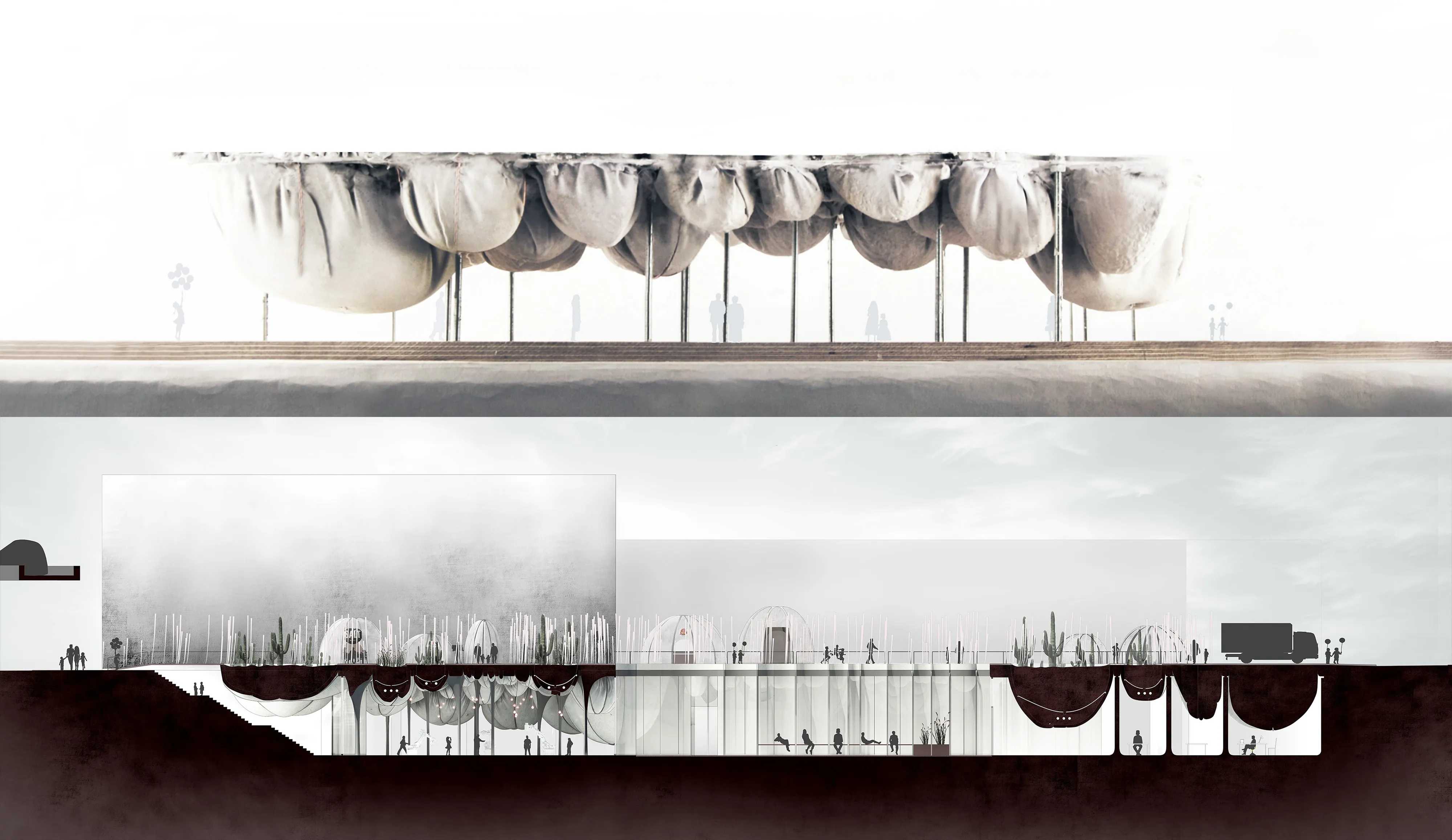
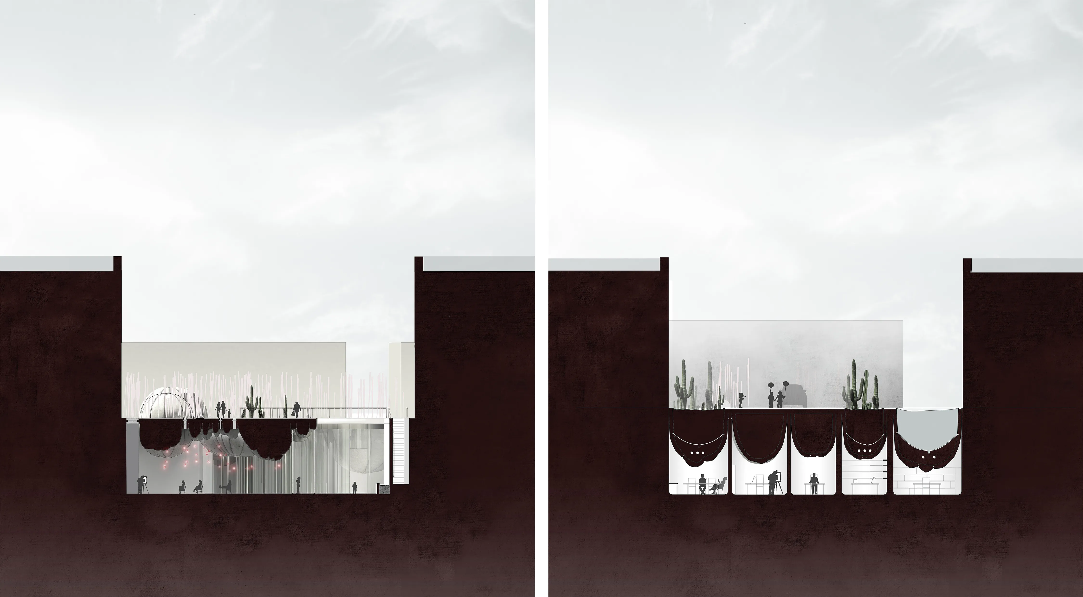
Located along the cultural corridor of Dubai, Al Serkal’s end of Sheikh Zayed Road, the aim was to push the project below ground and to create sunken courtyards that with the inverted structure create a spatial dialogue between the programs underneath and above, creating a coherent public landscape on the ground level.
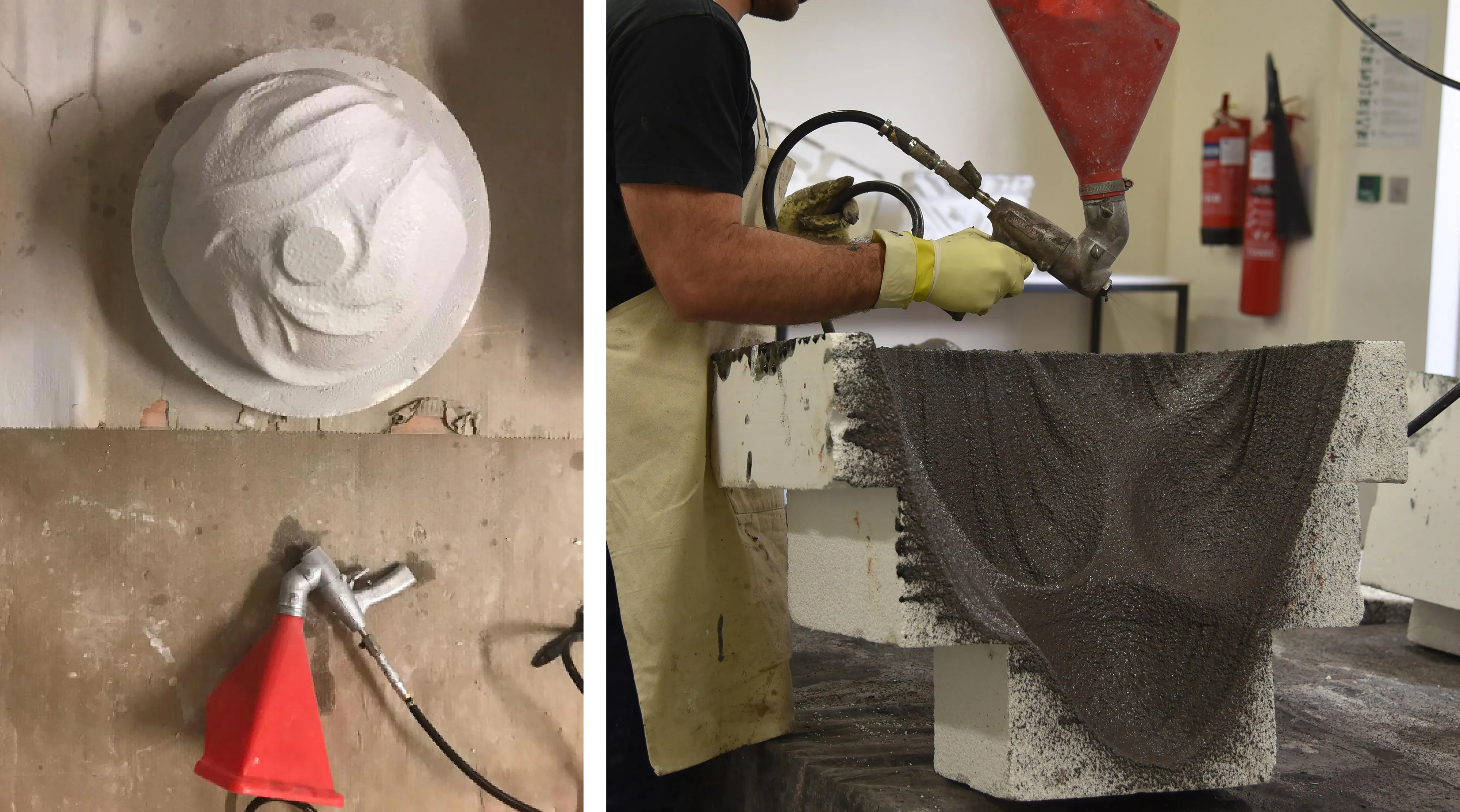
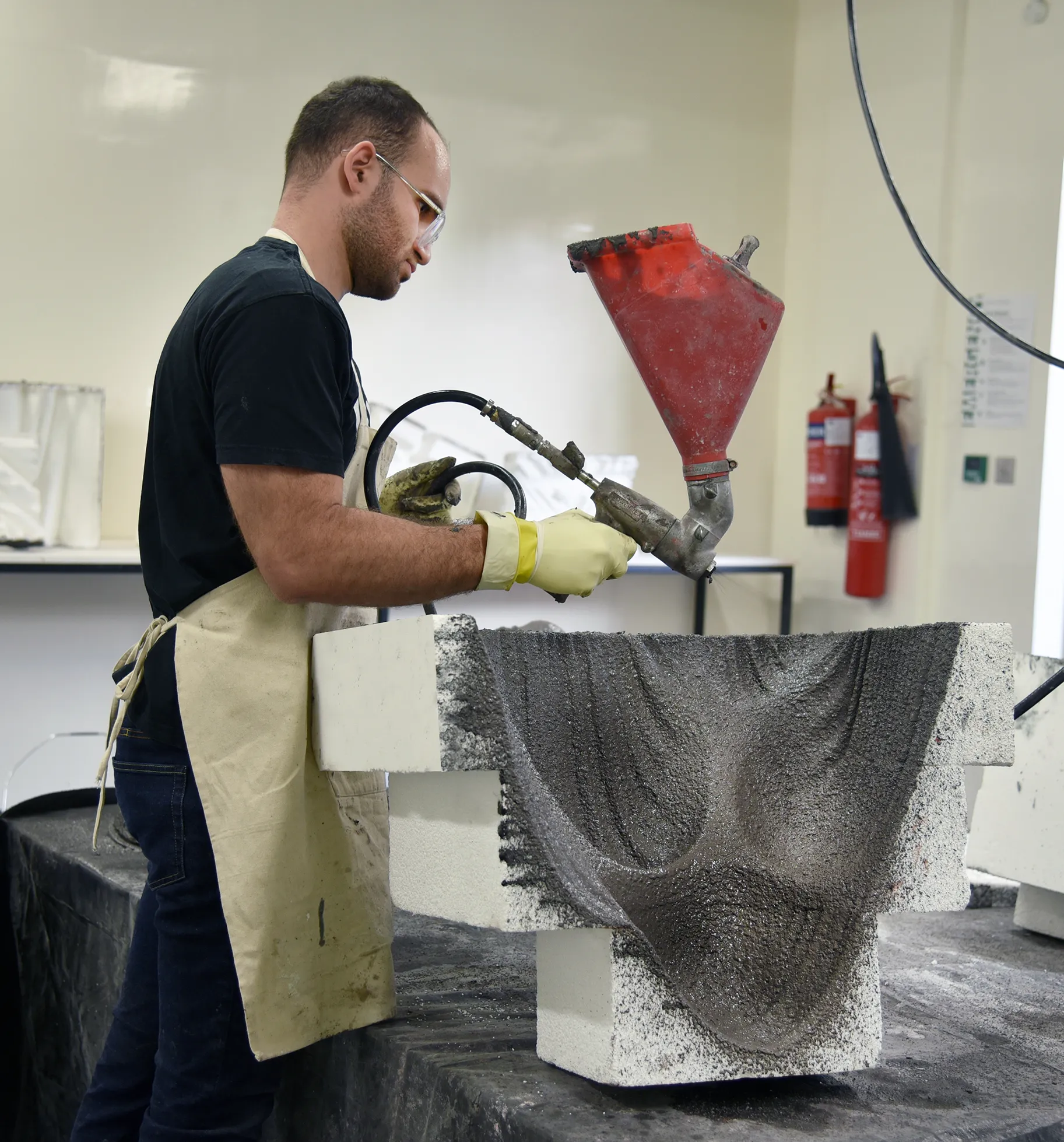
A detailed look at how the inverted dome structure and cast-in-fabric systems could be constructed in large scale scenarios.
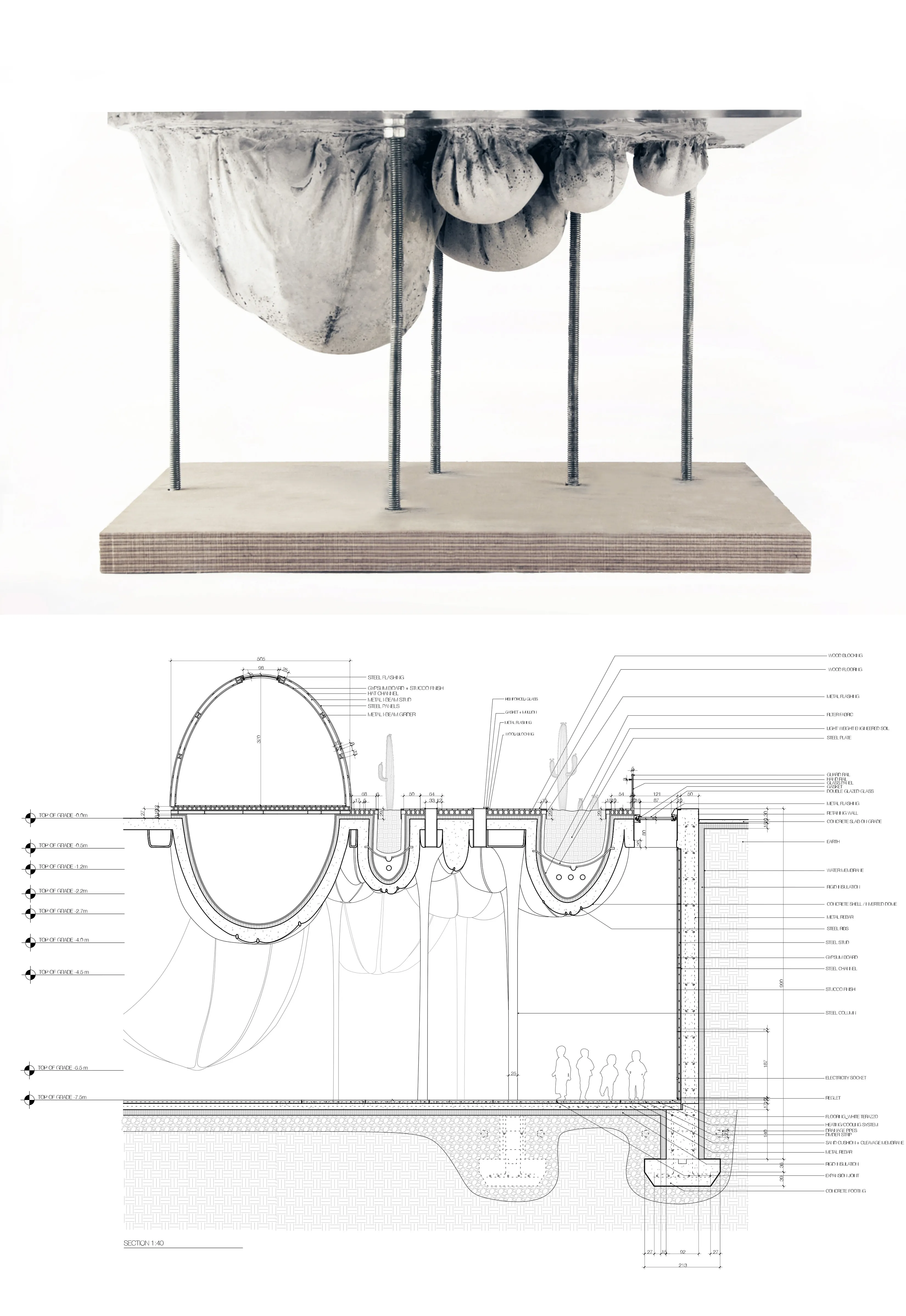
Investigating the spatial and experiential qualities of the design and material systems.
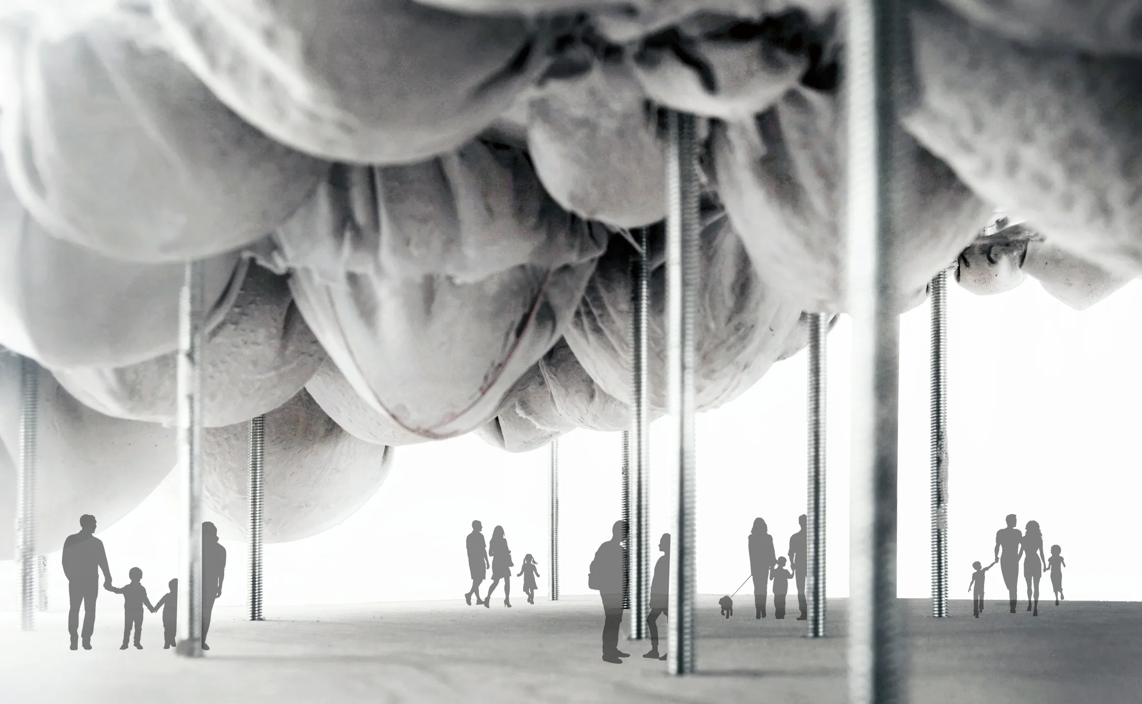
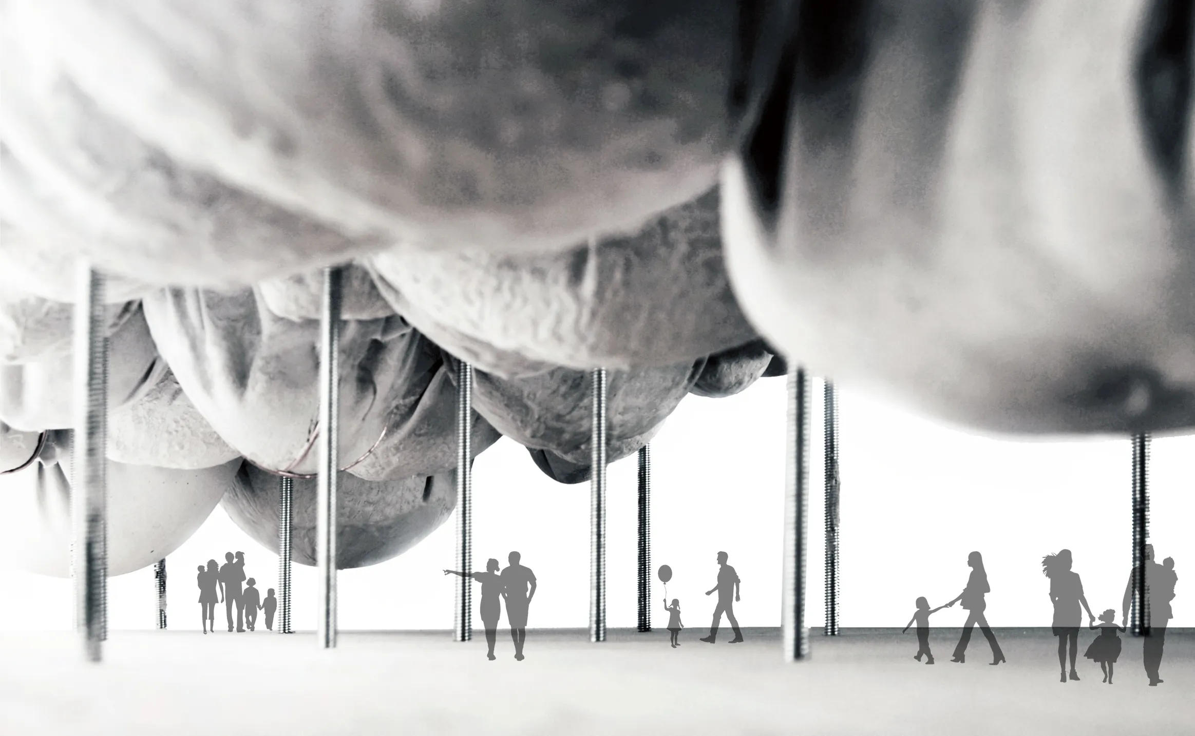
The project looks inwards towards a varying sizes of the volumetric domes creating a dynamic interior. As you walk down the large welcoming stairs, the project reveals itself and transforms from a massive and dense structure into an open floor plan void. Modules are subtracted to create the suncken courtyard voids.
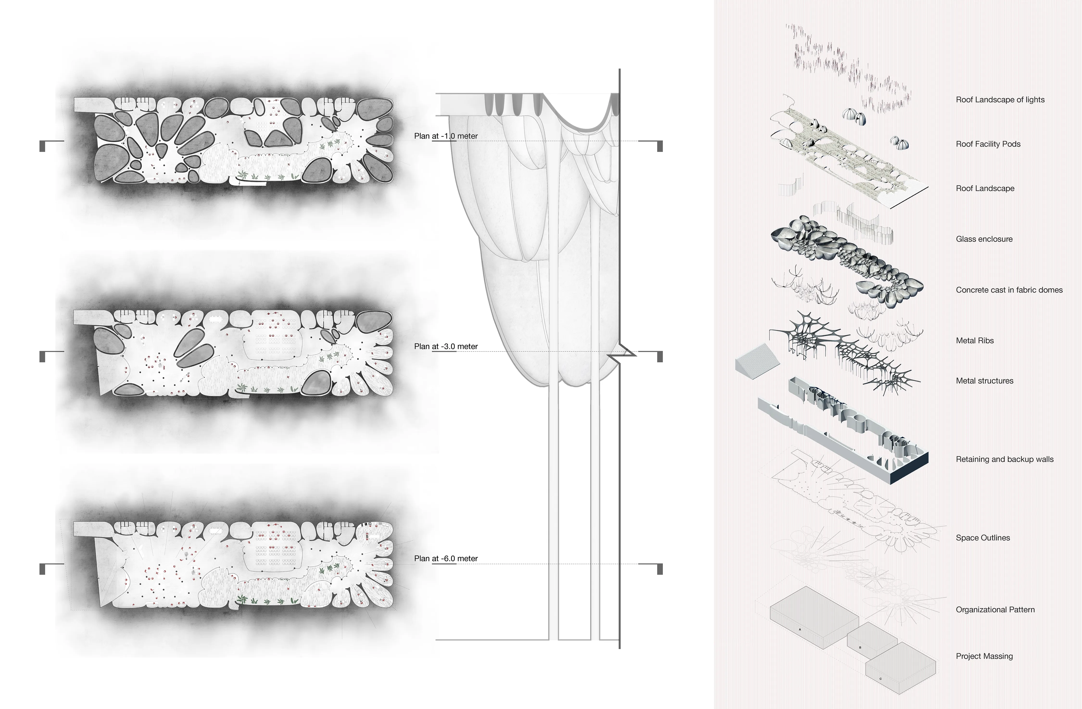
Longitudial and cross sections.
A technical inside look into the components of each system.
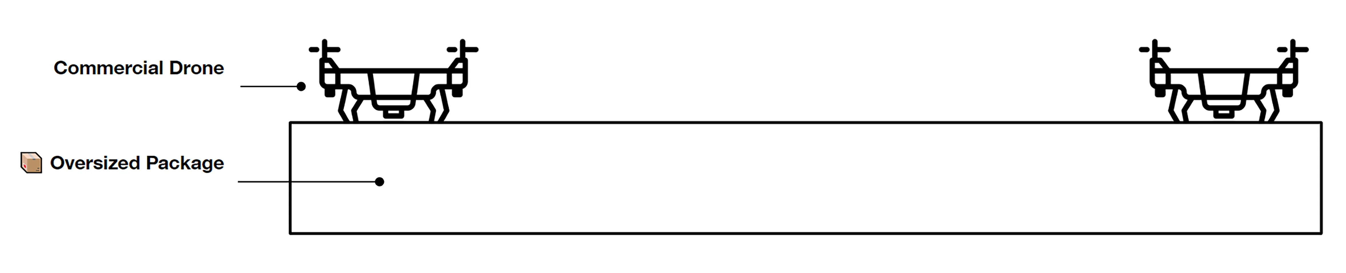
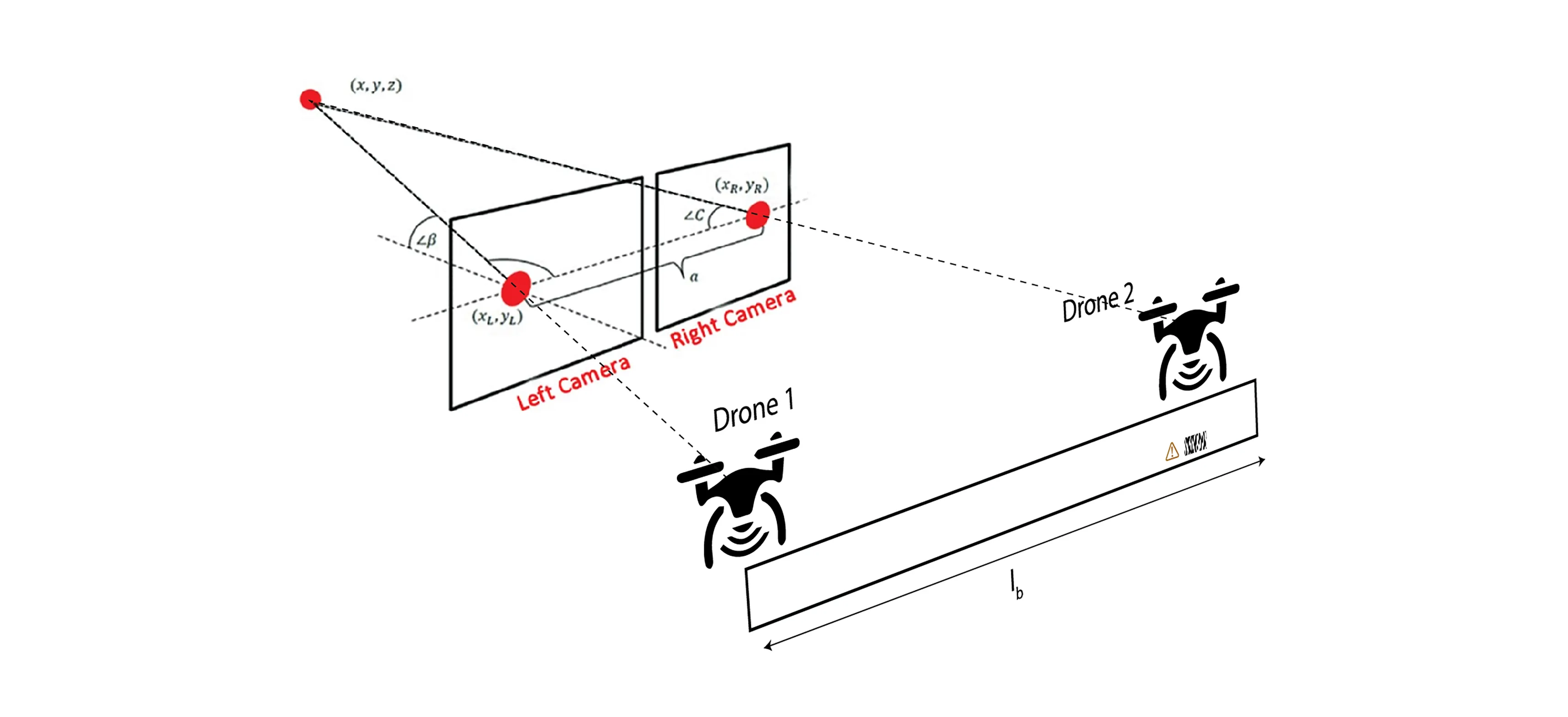
A growing demand for drone systems in highly constrained indoor environments - especially warehouse inventory management.
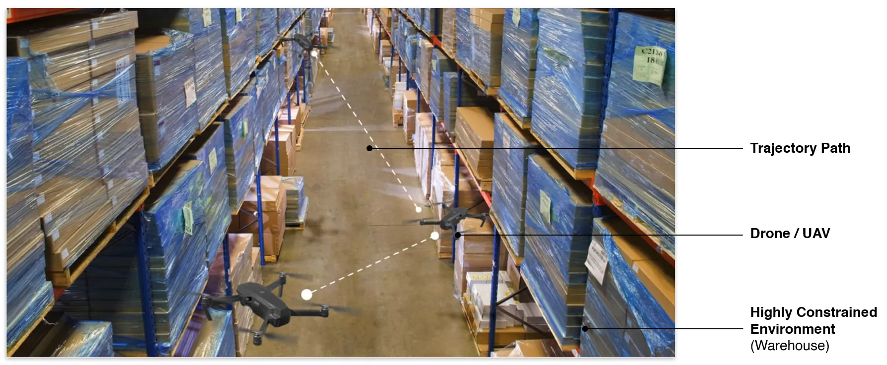
The use of single drones may lead to payload limitations that are proportional to their size and hardware. More powerful and larger drones might prove to be expensive and unscalable.
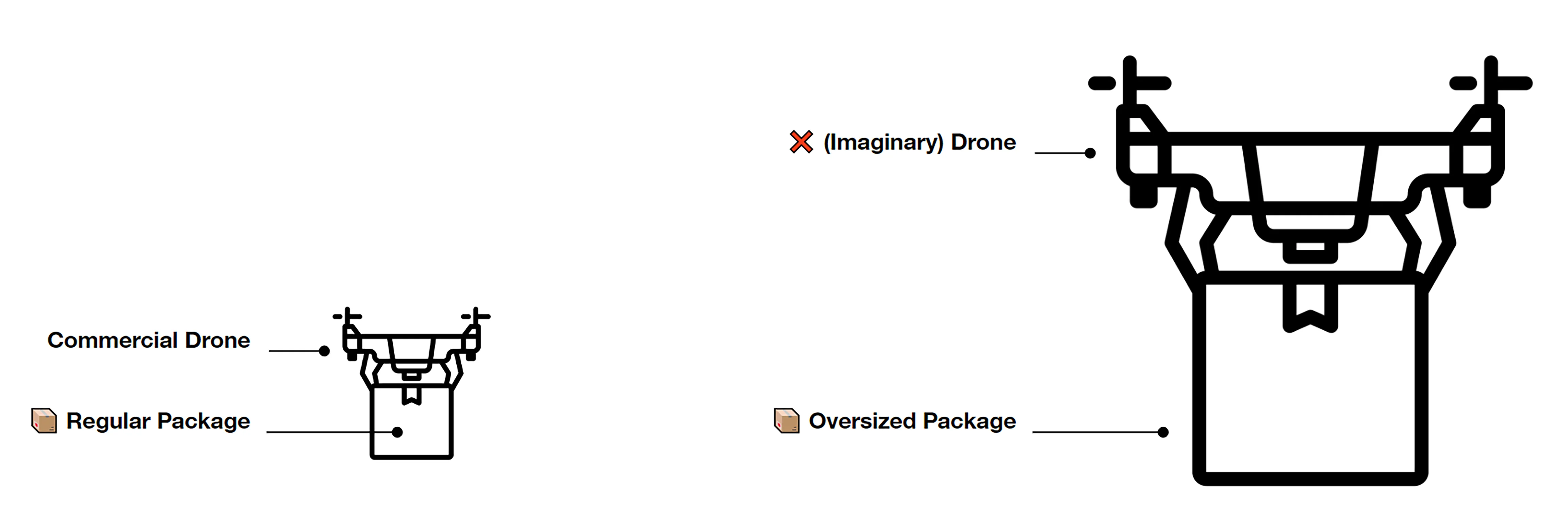
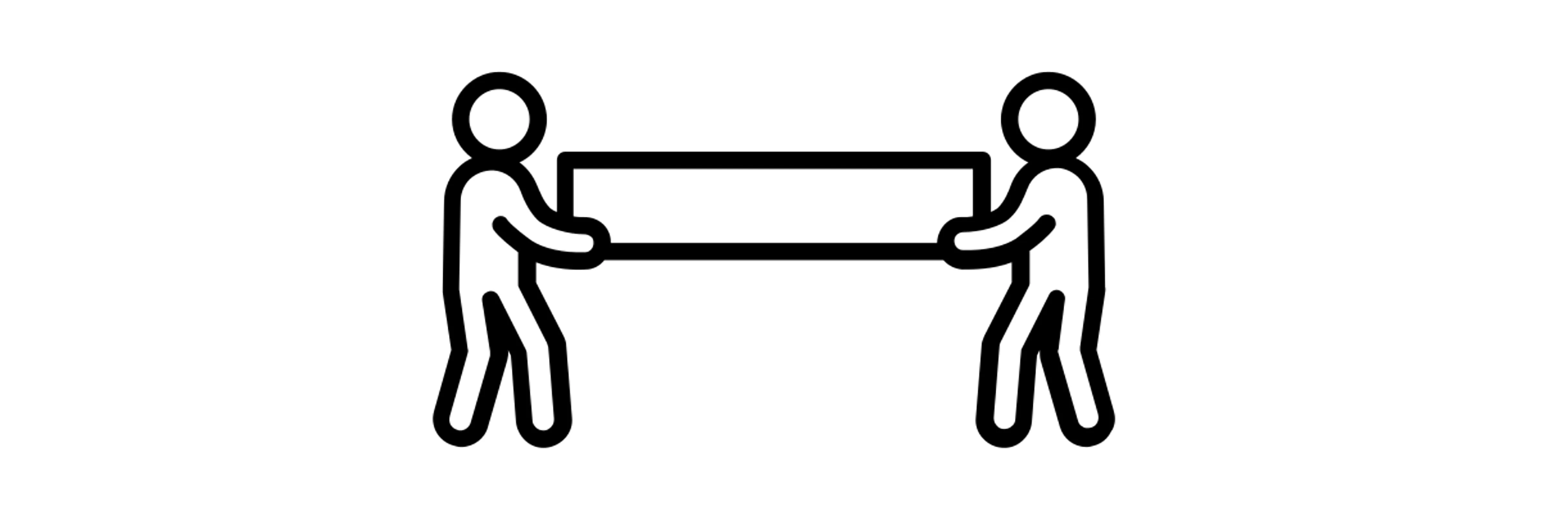
Warehouses can make use of multiple small drone swarms with a simple rgb camera for moving large payloads together.
🙄 We’ve always done it this way..
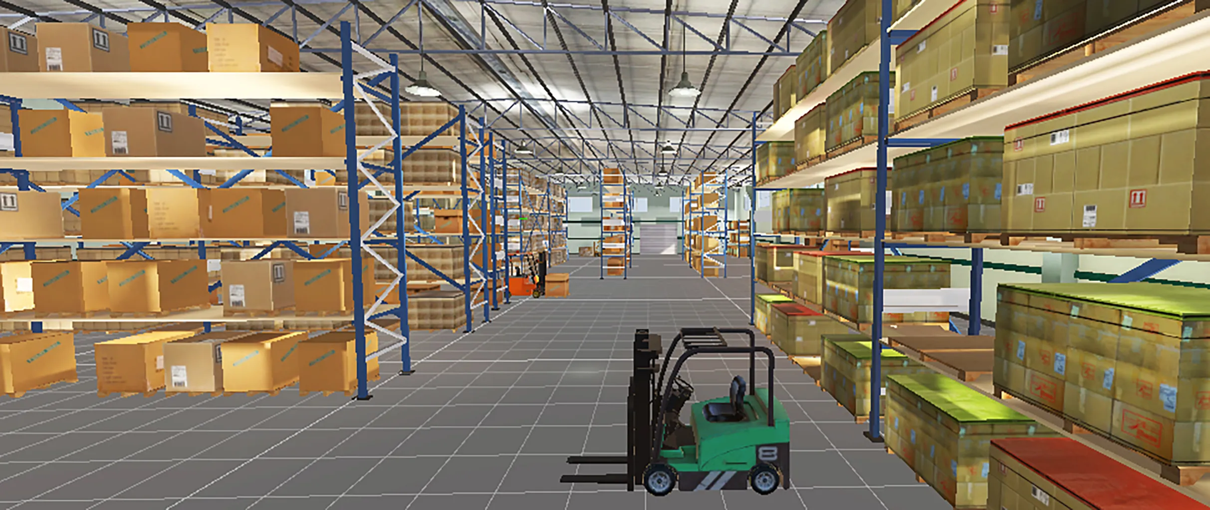
Where human driven navigation might not be possible or efficient - autonomous drones are seen as a highly valid solution.
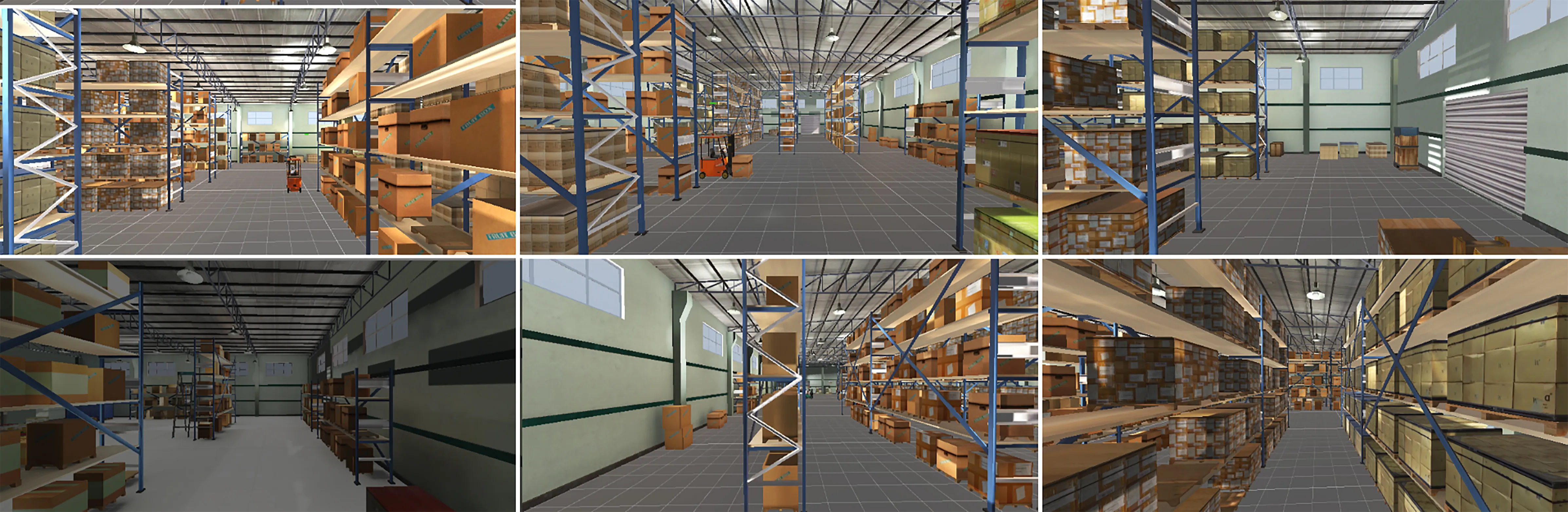
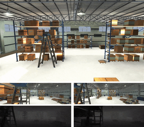
We use digital-twin drone system and simulated virtual warehouse environment as our source of data.
This is to tackle the data unavailability and manual annotation tediousness problems.
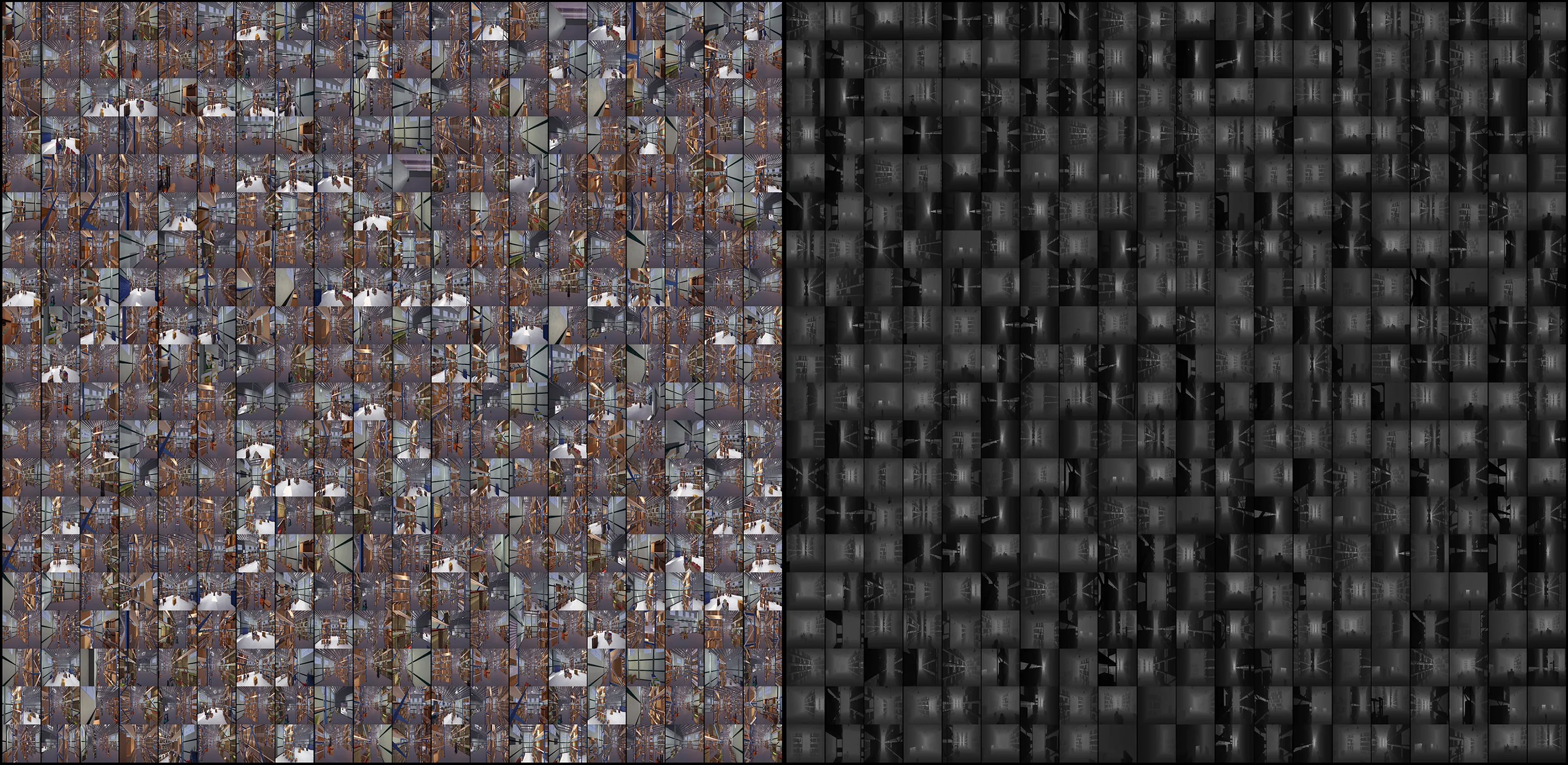
We create a simulated environment of a large warehouse in Unity3D platform. We make sure we mimic lighting, materials and textures to real warehouses.
We develop a digital-twin of the drone - that mimics an actual drone in terms of physical, technical and visual features. We create the digital-twin of the whole two-drone system with payload.
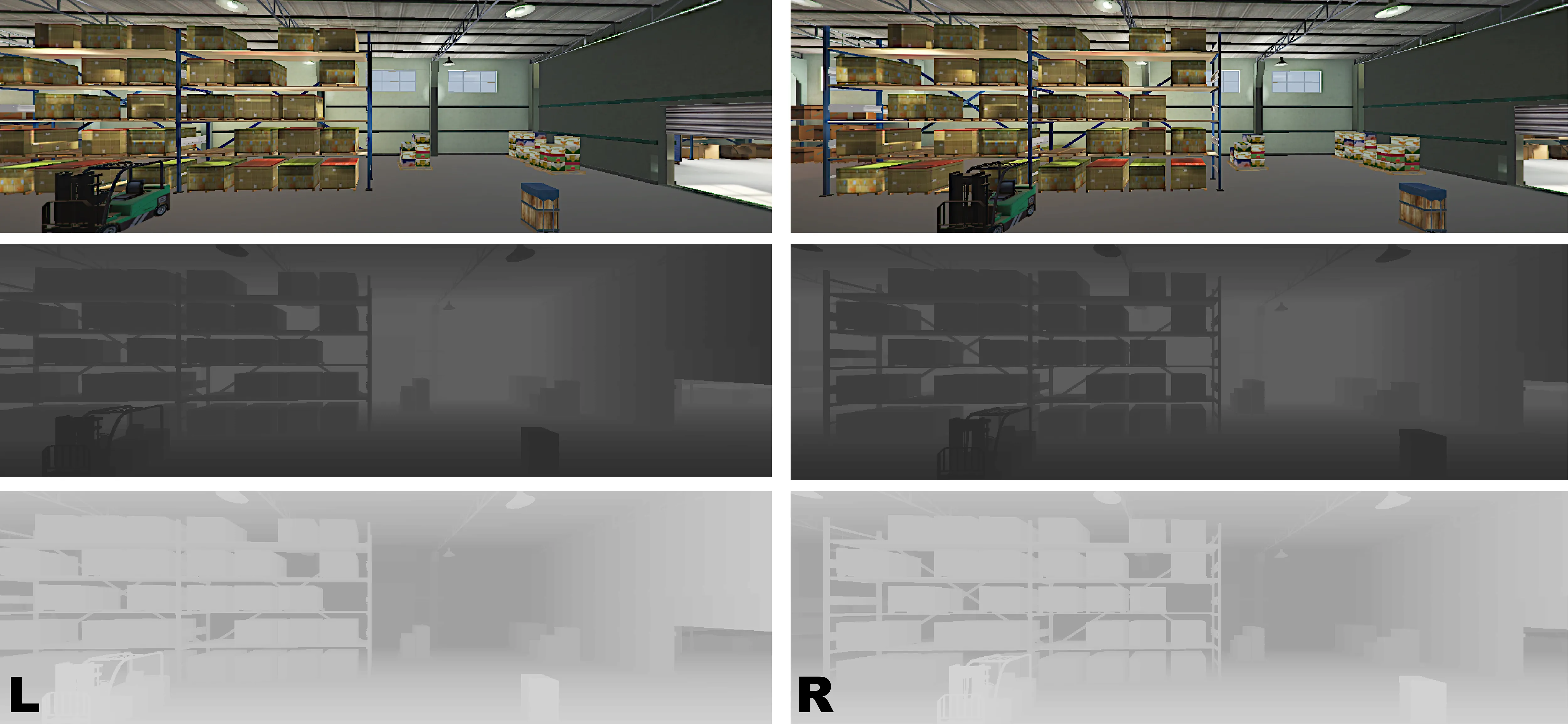
We setup virtual RGB sensors on each digital drone to collect our input data
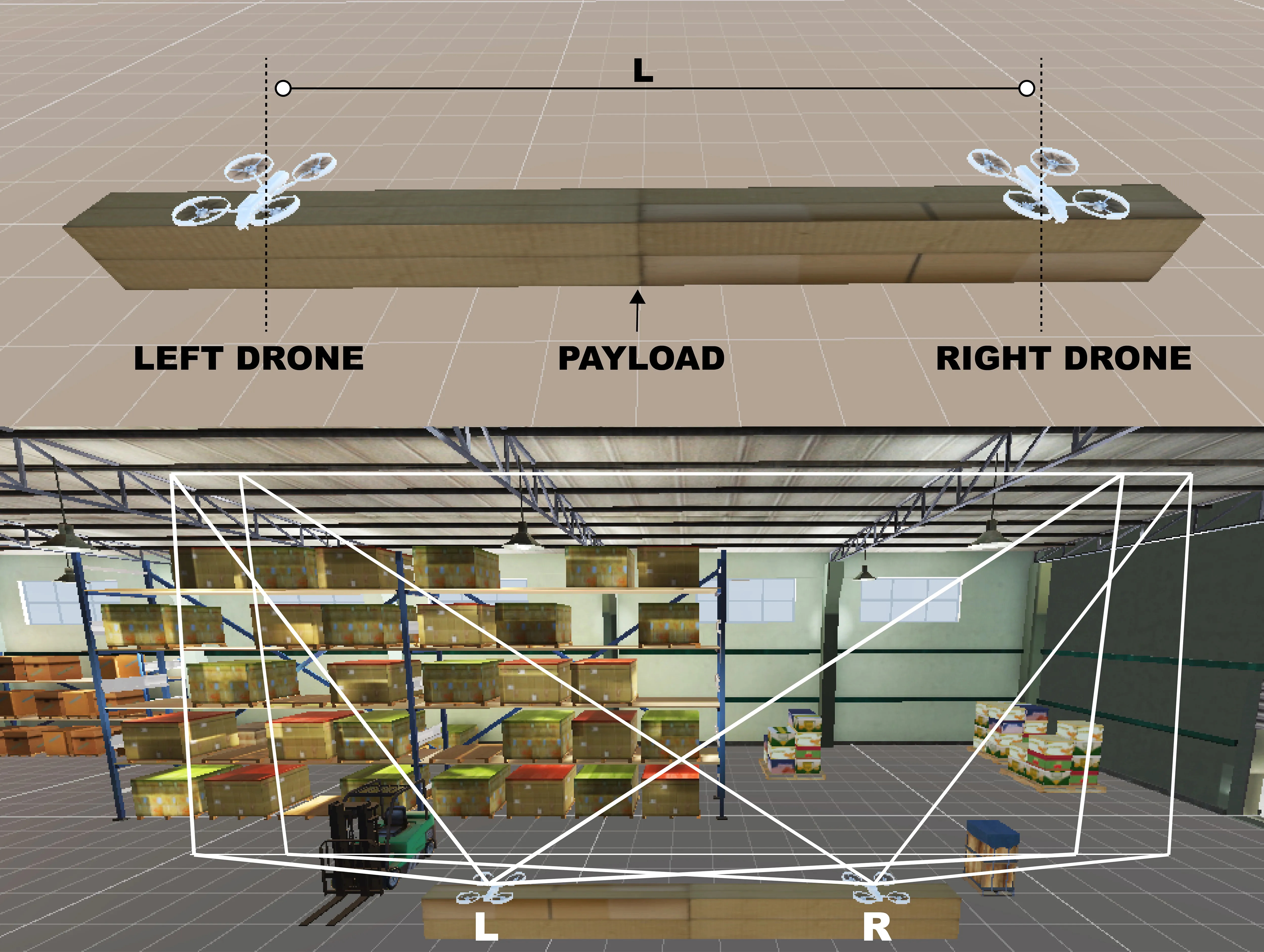
We recognize the resemblance of a two-drone system to a stereoscopic vision system. We use CNN to stereo-match and in real-time, we reconstruct the environment that is immediately in-front of both the drones.
Since we consider the input pipe-line to be a stereo-vision system, the two-drones can perceive all non-occluded obstacles “seen” by both drones.
To gain diversity in data collection, we capitalising on the simulated environment, by creating a procedural generation algorithm, that randomizes our environment for each run.
→ We randomize obstacle positions, orientations, materials and textures.
→ We also vary environment lighting to diversify our synthetic dataset for diff. Illumination settings.
The digital-twin system (2 drones + payload) is completely physics informed.
→ We develop a depth shader to render depth maps along with the RGB images for each drone in the system.
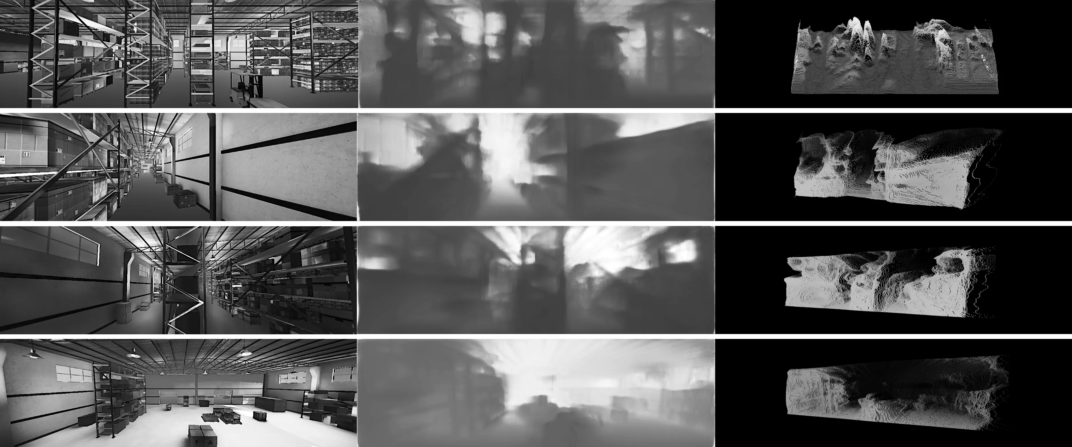
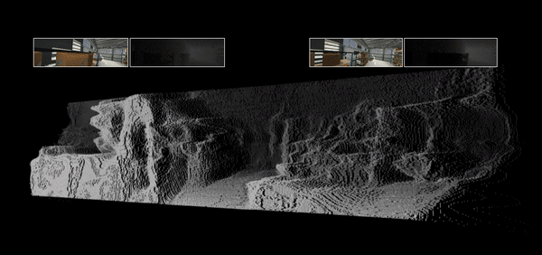
→The digital-twin system can be now used to explore the environment, capture input RGB images, and depth-map ground truth labels. We also log the Euler rotations.
- 1200 RGB images from left and right
- 1200 Depth-map labels from left and right
- 600 Euler rotations (camera odometry)
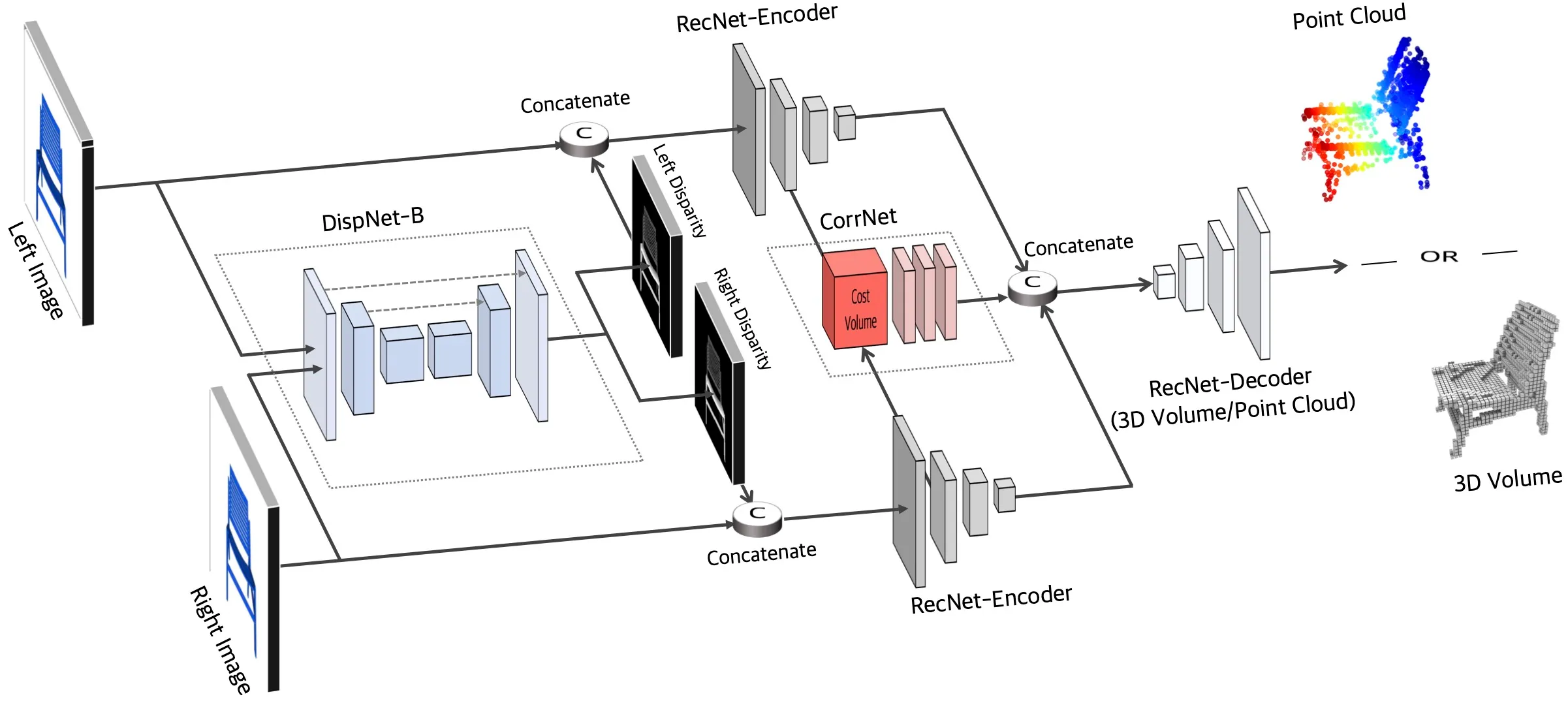
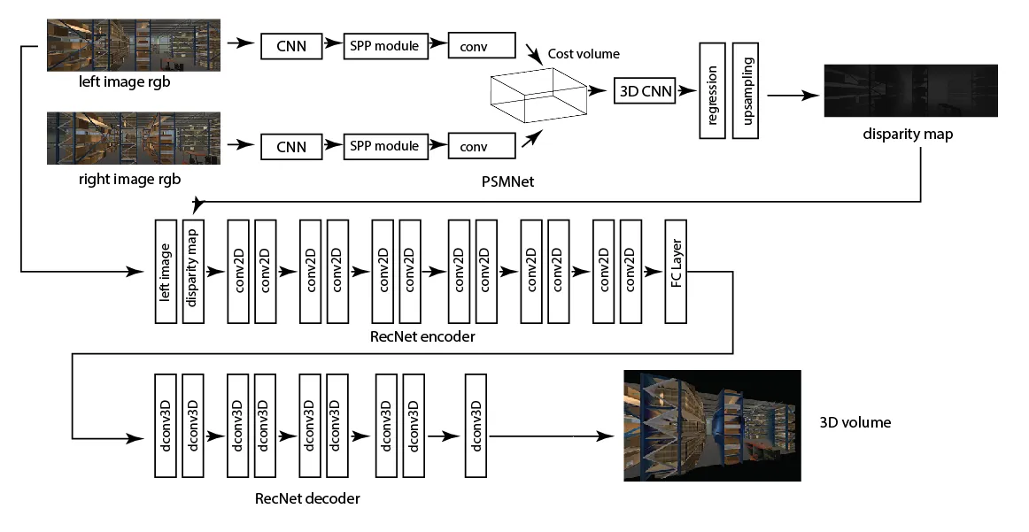
→ We study two CNN architectures, PSMNet and RecNet (deep learning for stereo-matching).
→ We build a custom CNN combining PSMNet for disparity estimation and RecNet for 3D reconstruction.
→ We use PSMNet for the first part as it helps in efficiently extracting image features - like edges or textures - that can be used to predict the disparity more accurately through feature matching.
→ We use our synthetically generated RGB images from the left and right drones as inputs and the generated depth-map labels as the targets and train the PSMNet model to estimate disparity.
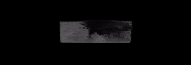
→ We then use the RecNet architecture to reconstruct the 3D model of the environment from the output disparity image from PSMNet. The overall trained model should be able to reconstruct voxel environment given a stereoscopic RGB image-pair as input.
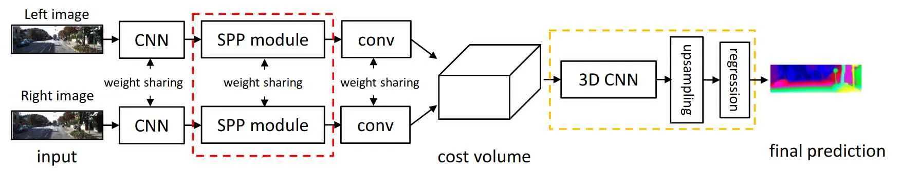
→ The RGB stereo images are input to a CNN that calculates the 2D feature maps in the images. Both the left and right images go through a CNN module for feature extraction and these two modules have weight sharing.
→ Then, they pass through Spatial Pyramid Pooling (SPP) modules that harvest these features and converts them to concatenated representations of different sizes. They are then passed through a convolution layer for feature fusion from previous layers.
→ Then the image features from both sides are used to from a 4D cost volume which is fed into a 3D CNN for cost volume regularization and disparity regression to get the disparity map prediction. They are evaluated with smooth L1 loss.
→ Then the disparity and the RGB image are fed to RecNet, that includes 6 convolution layers, one fully connected layer, and 7 deconvolution layers to finally build the volumetric mesh.
→ We initially 60-40 split as training and testing data-set.
→ We implement the training using the PyTorch library.
→ For training, we train with Adam optimizer with a learning rate of 0.01.
→ During the training process, the images and labels are randomly flipped horizontally and vertically for 20% of the data samples. The maximum disparity was set to a 50m.
→ We started from the pre-trained PSMNet model and trained with our training data-set for 100 epochs with a batch size of 10.
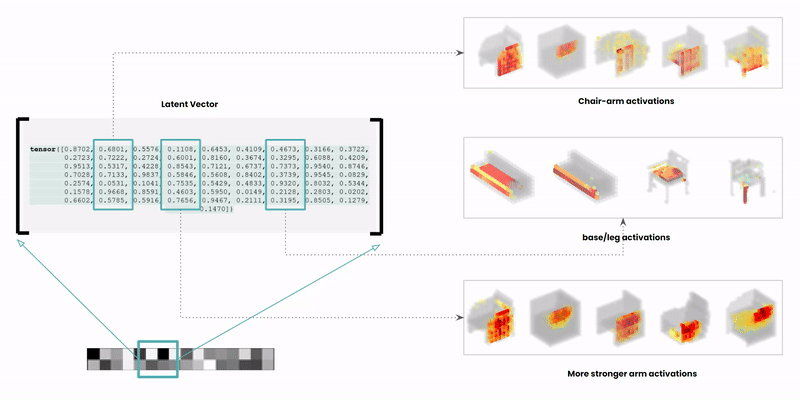
The latent space is a high-dimensional collection of numbers. These numbers define positions in the shape field (imagine like a frame in a video).
Specific (groups of) numbers correspond to specific ‘parts’ of the output shape.
Reference: Learning a Probabilistic Latent Space of Object Shapes via 3D Generative-Adversarial Modeling @CSAIL https://arxiv.org/pdf/1610.07584.pdf .
Reference 2: https://www.computationalarchitecturelab.org/ (accessed dec 2022).
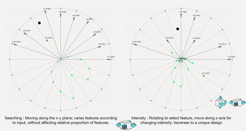
For a designer to understand, interpret and control navigating a shape field (latent space), we need to design an interface between the designer and the AI. This interface needs to synergically support the designers’ creative process of association, exploration and visualisation.
To remove any medium-induced cognitive loads, we design a simple 4 axis tangible interface and a supporting visualizer for the designer to ‘design’.
The process involves two actions:
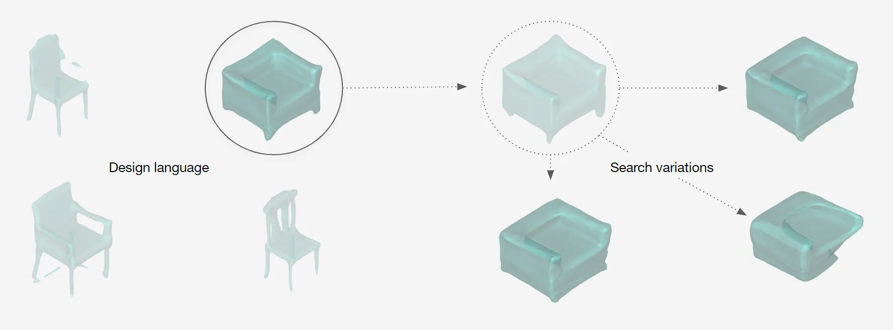
Control Interface: We design a 4-axis regularized interaction space that a user can control using a spacemouse (3dconnexion.com):
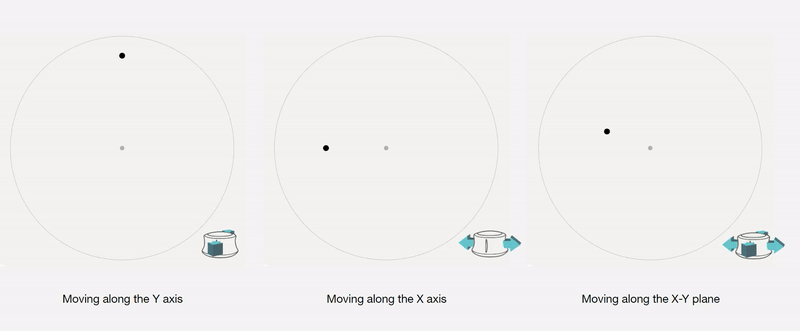
We then map the latent vectors from the space field as follows:
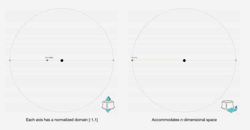
Along each vector axis, an intensity factor is controllable as given below. The intensity factor determines how much influence each dimension has.
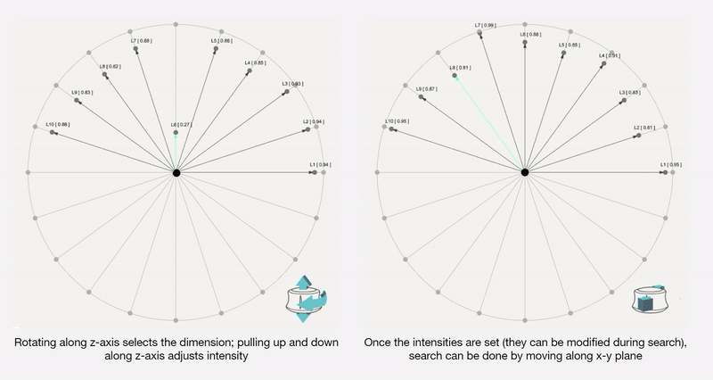
Adjusting the intensities changes the relative-proportions of each feature. The search maintains this relative-proportion, but varies it periodically.
For a standard vanilla GAN, we have a latent dimension of 64. The working of the input system for this latent space is illustrated below.
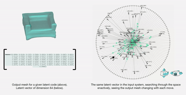
We also map and record the output mesh in the corresponding location on the axis of input. This is done in order to also understand spatially the trace of the design process; this is in case the designer wants to retrace steps, etc.
The below diagram shows an example design process and simultaneous mapping into the spatial domain.
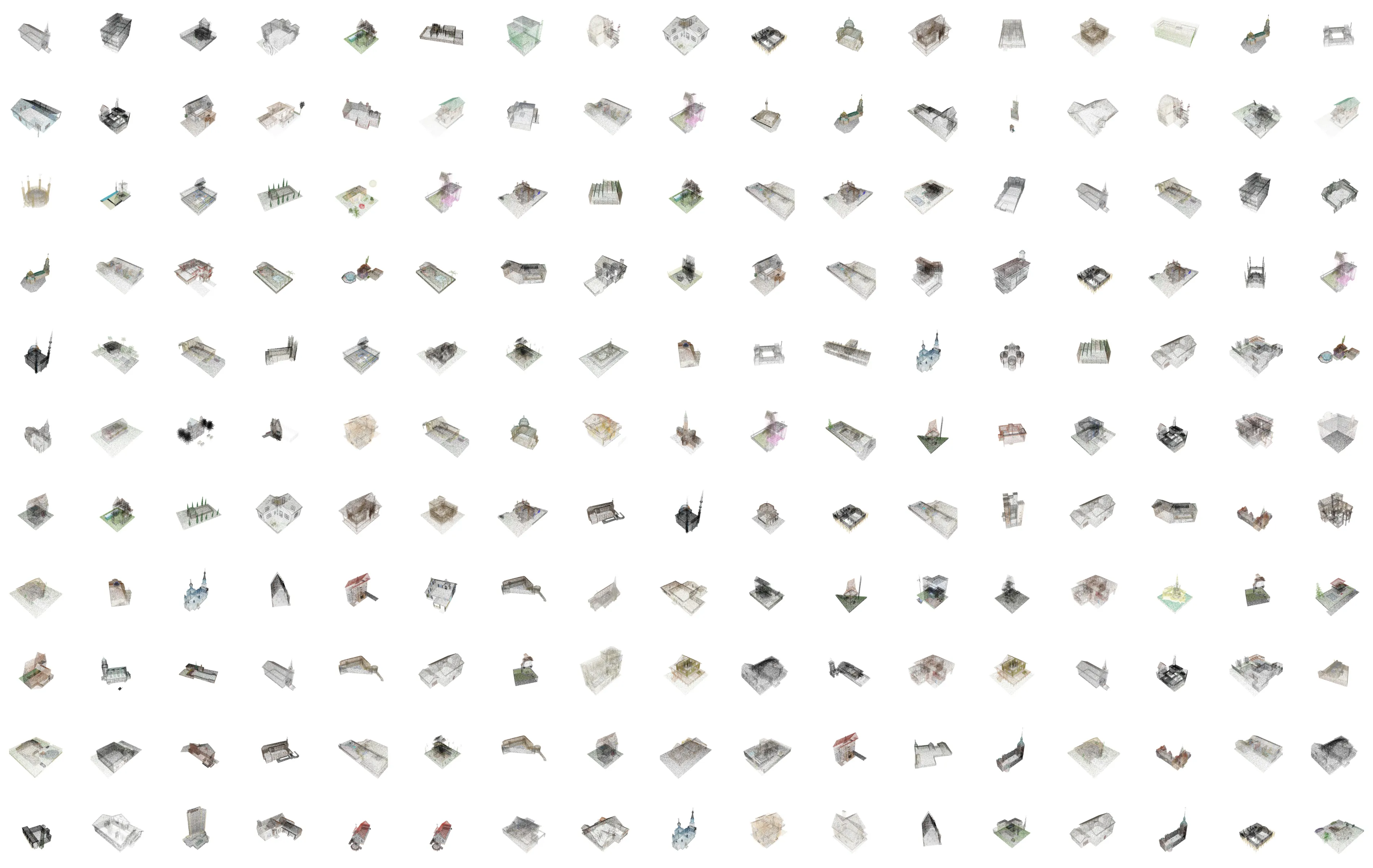
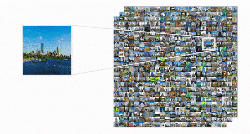
Curating a dataset of architectural buildings.
2,000 3d models of residential, religious, commercial and government buildings.
Neural implicits: using a simple MLP to encode 3D geometry.
There are of course the obvious suspects: meshes, point-clouds, NURBS, voxels, etc. However, there is another powerful way to represent 3D geometry: functions that define whether or not any point in the 3D space is inside or outside of the geometry described.
A function that takes in a point and output its signed distance to the surface of the geometry.
Using physics engines to inflate geometry based on vectorized pressure and material deformation to pack within one another vertically while maintaining control over composition and program distribution.
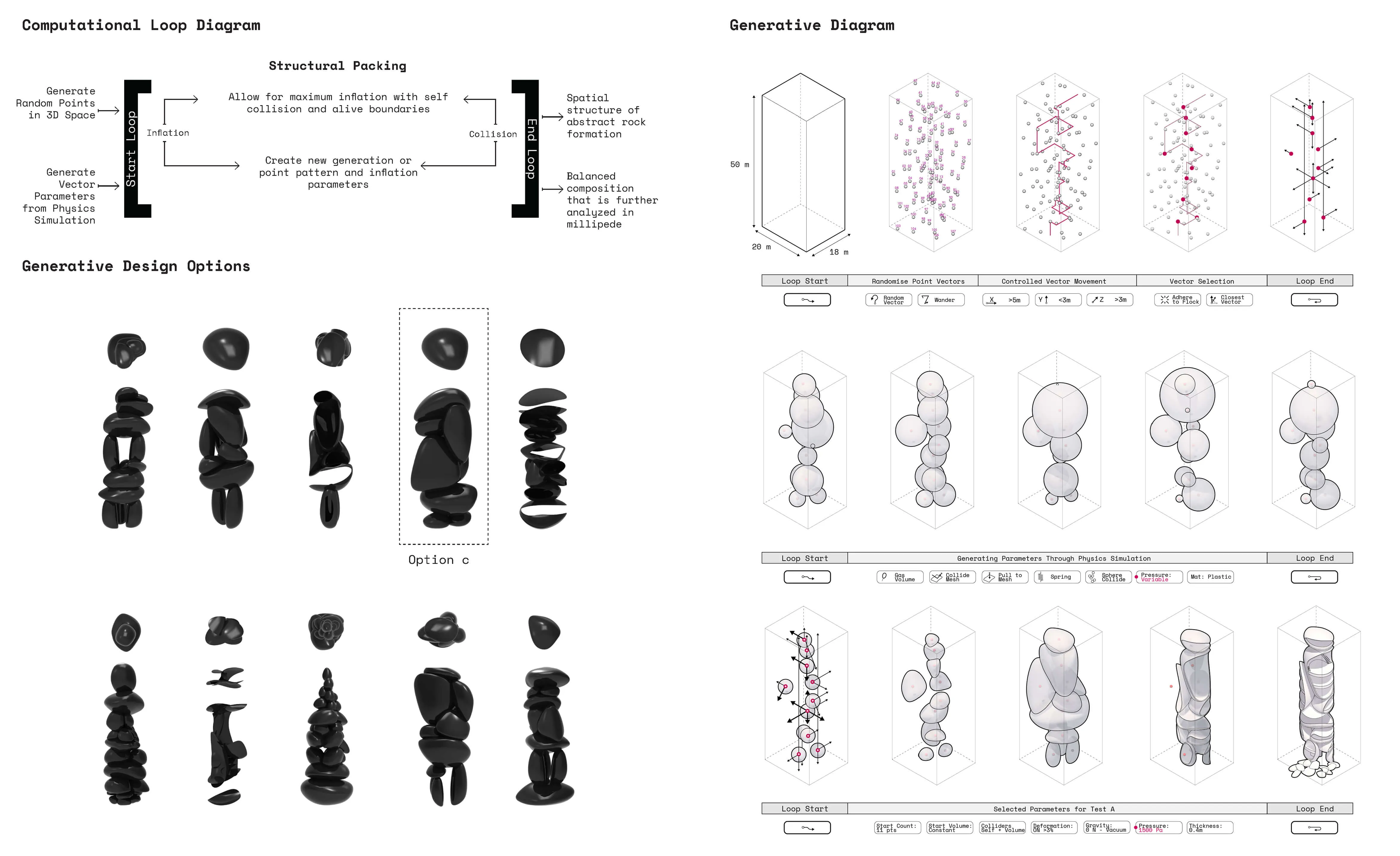
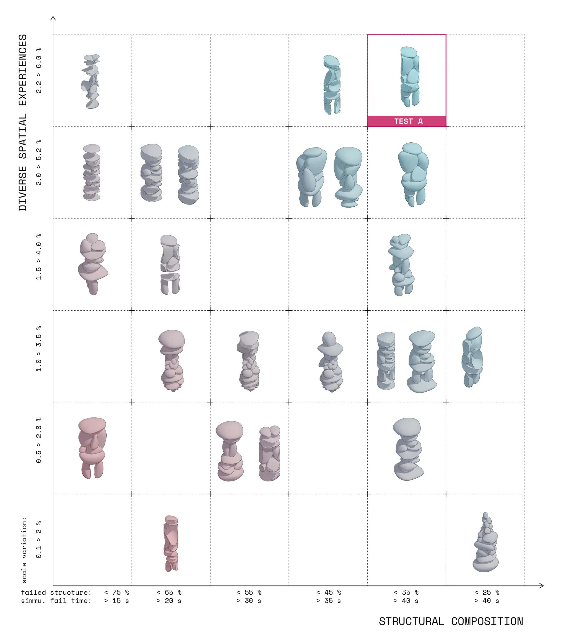
Plotting the generative compositions to qualitatively and quantitatively measure spatial composition and structural stability.
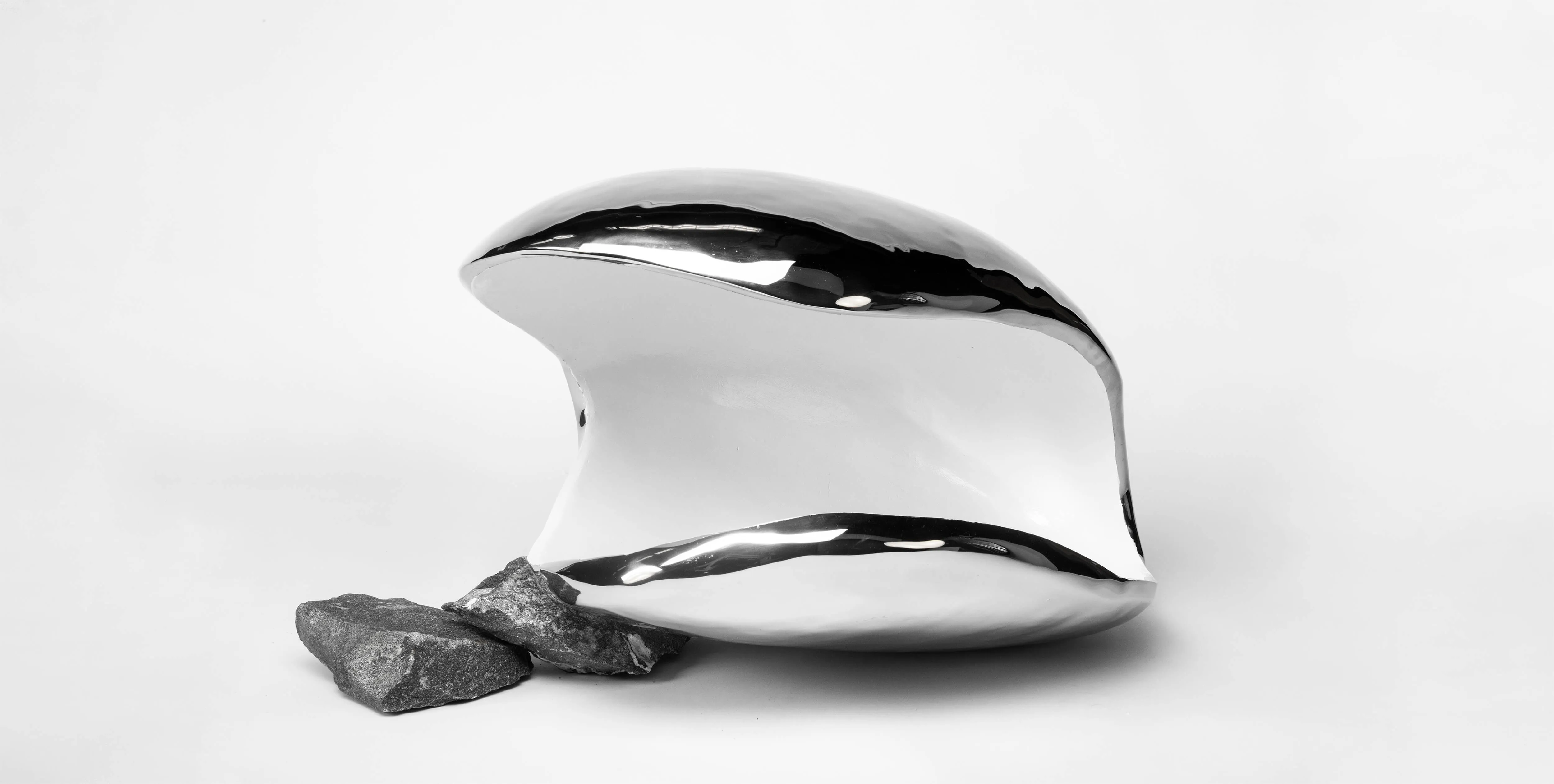
Selecting segments of the vertical observation tower structure to understand material fabrication using non-linear design to digital tools processes.
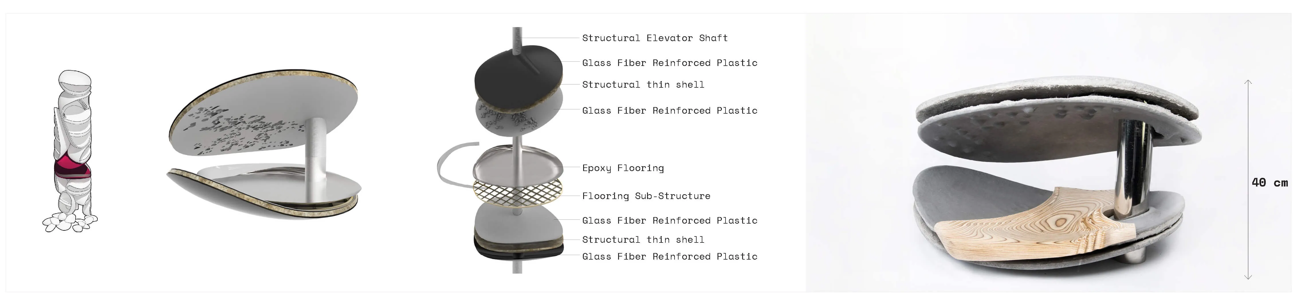
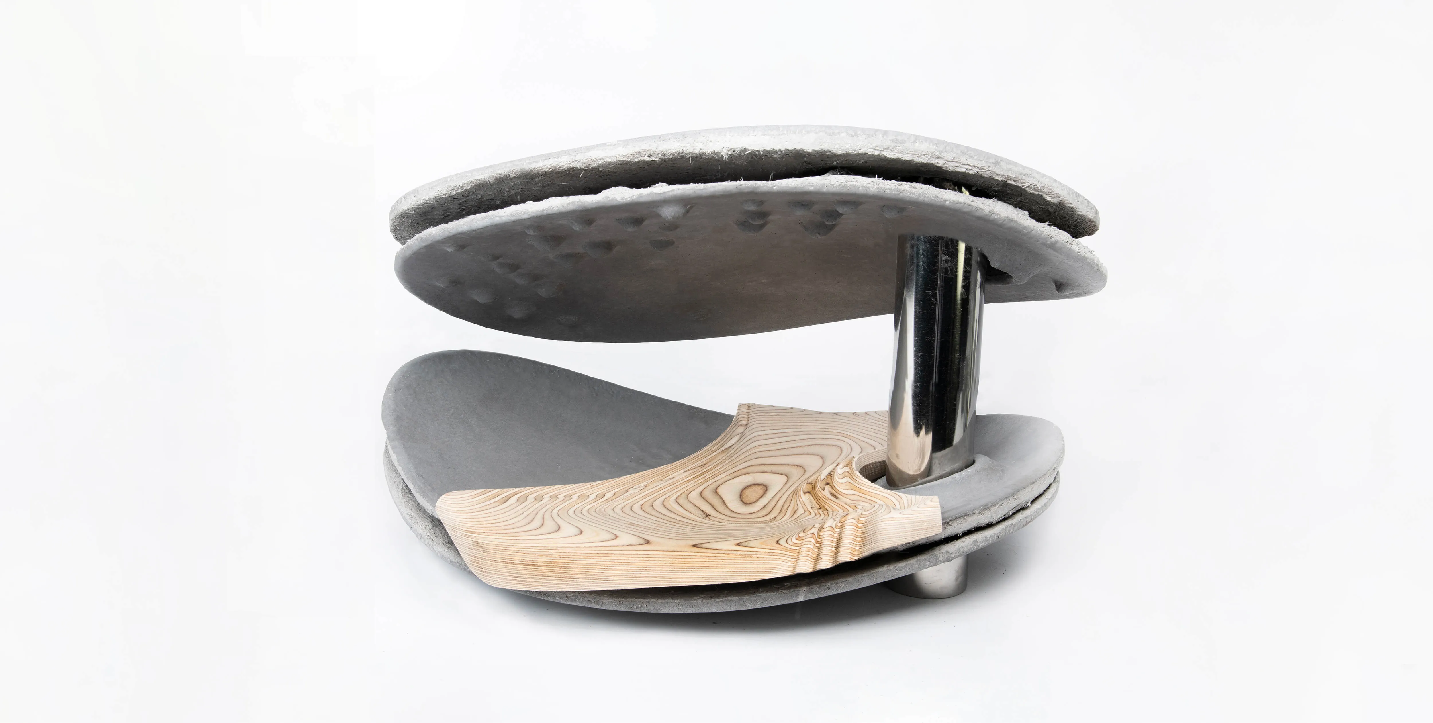
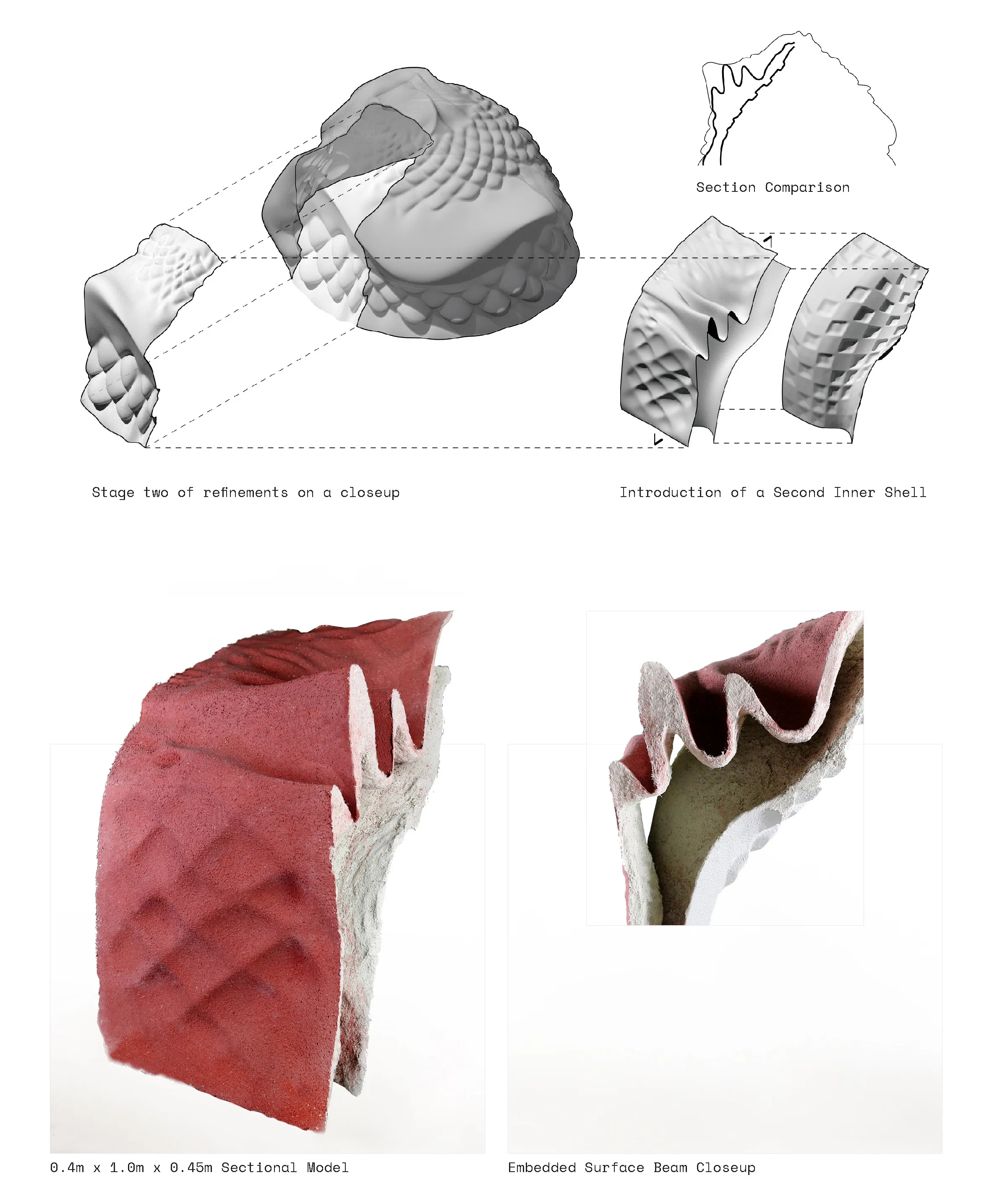
First, a double-shell structure sandwiches a stress capable metal outershell that wraps around a GFRC interior envelop.
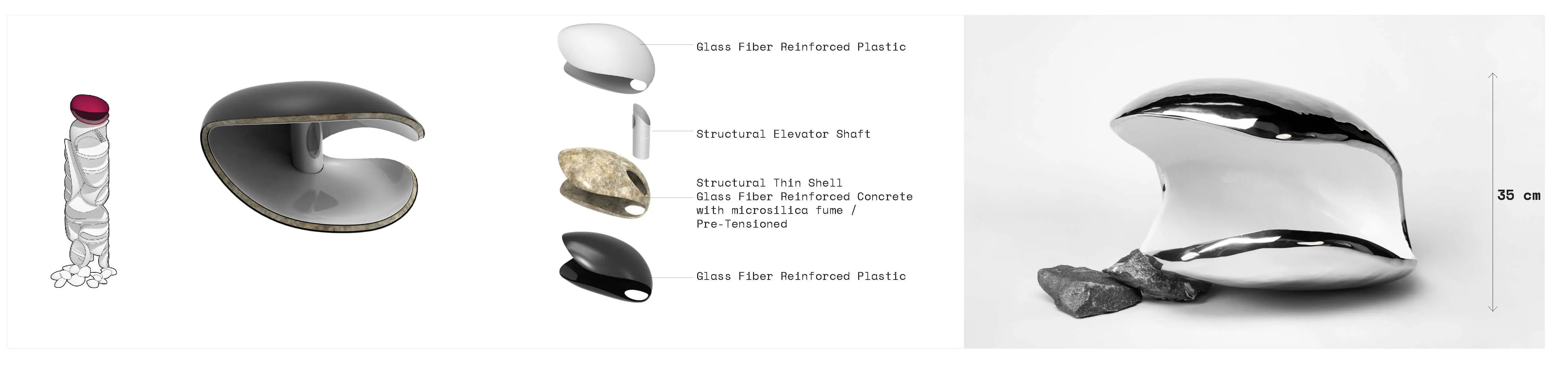
Second, a decorative GFRP panel wraps around a GFRC shell with custom material deposition along ribs that are generated in an FEM structural analysis.
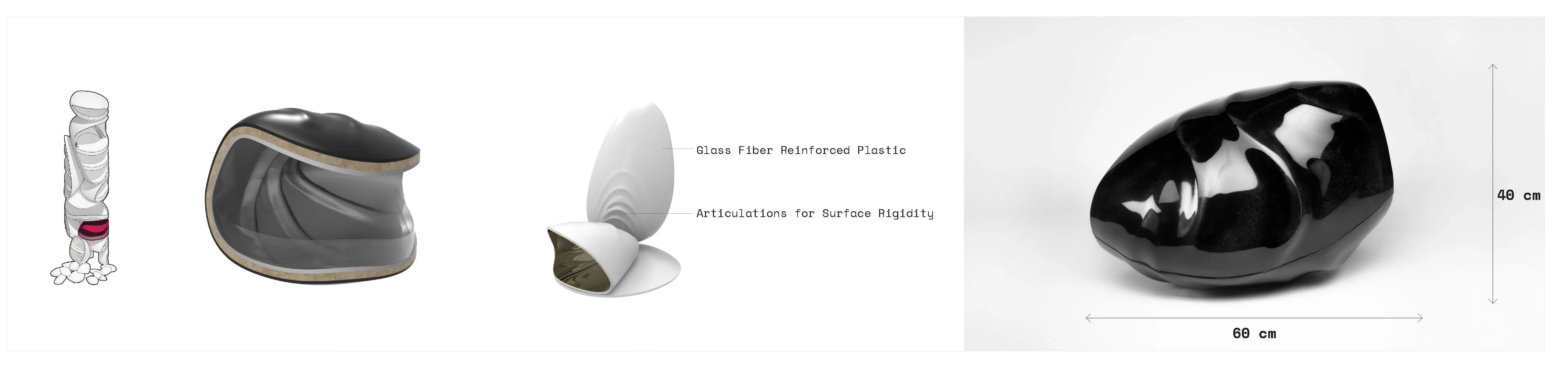
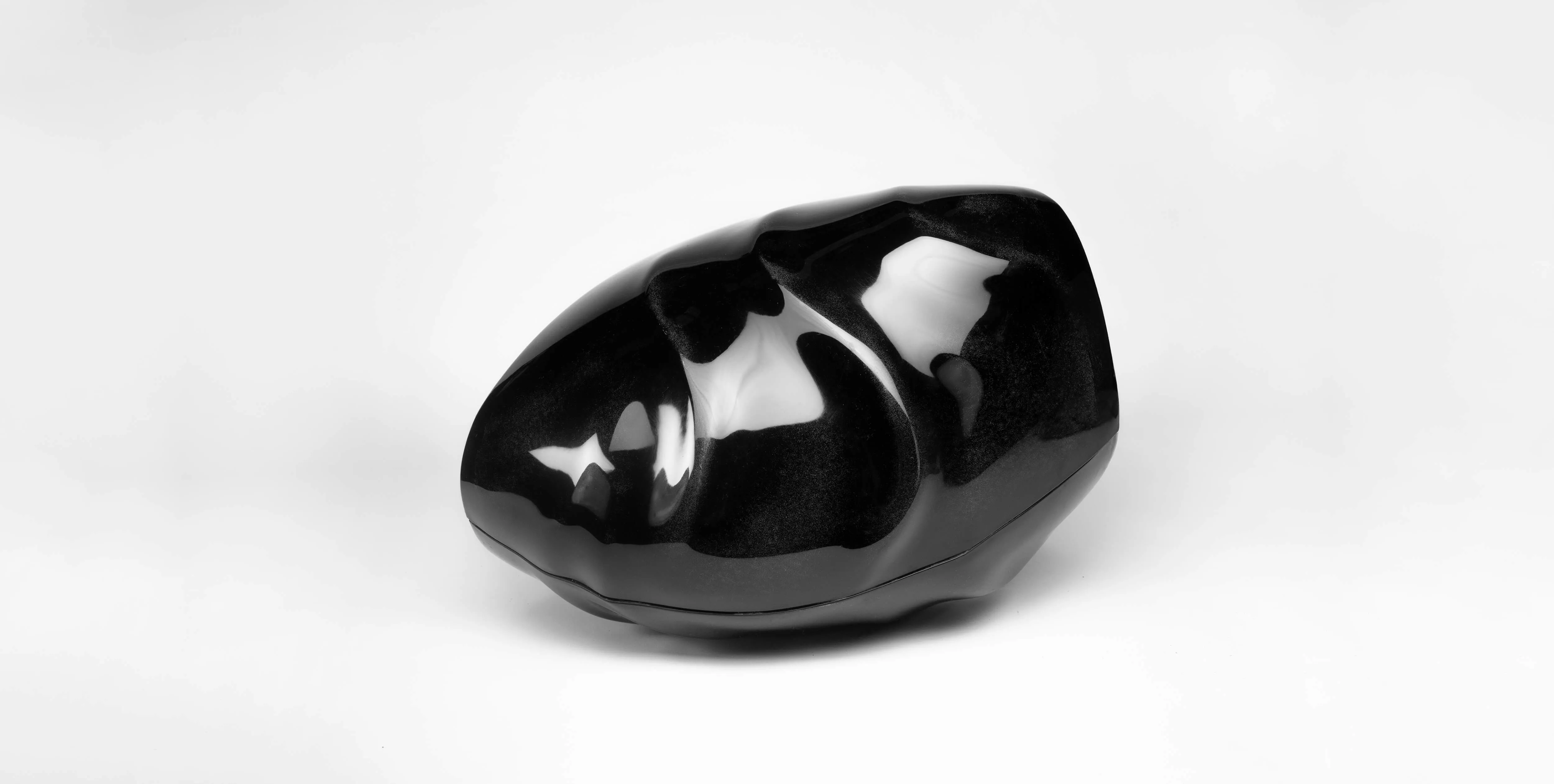
Last, using a network of post-tensioned steel members to enable the cantilever of large surface spans. The web network of cables are hidden inbetween the two shells and forces are directed to ground through a solid compression column.
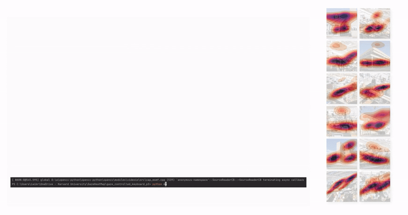
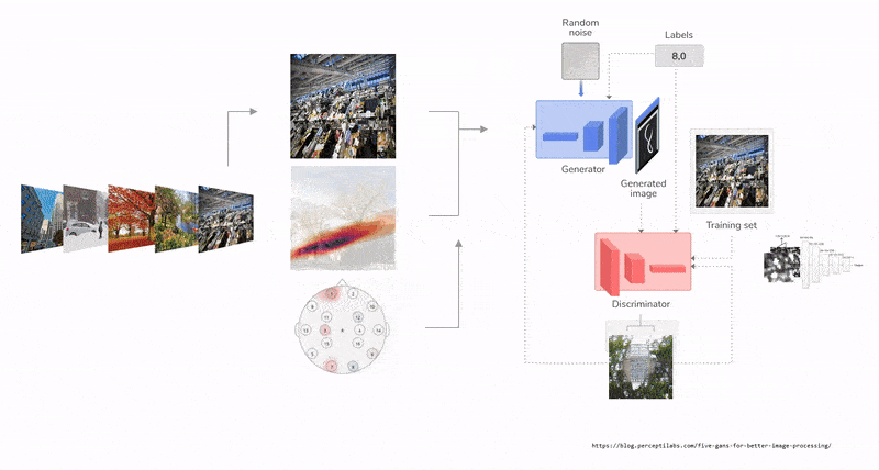
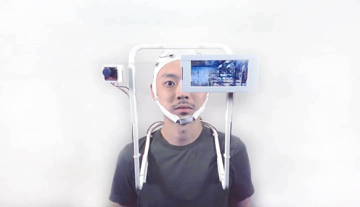
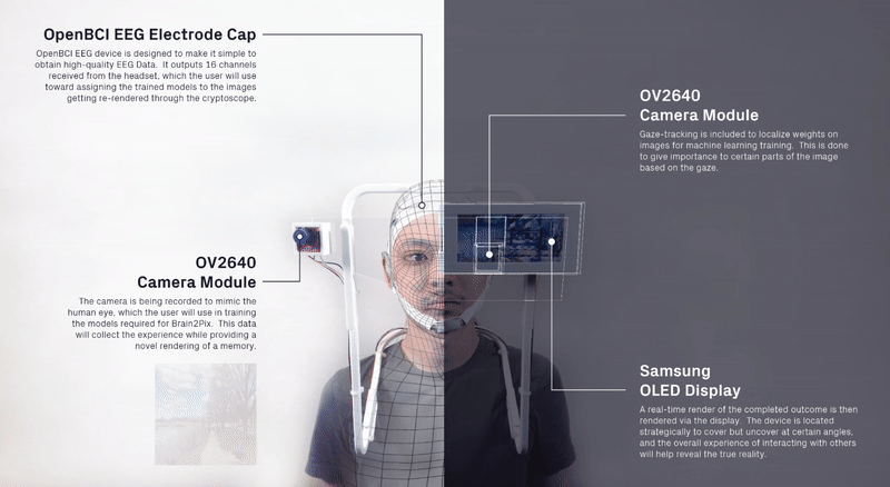
We curated a data set of momentsthat could resemble possible memories, such as the trays at the Gund Hall,identifying all four seasons, skylines in NYC, etc.
Plotting the generative compositions to qualitatively and quantitatively measure spatial composition and structural stability.
Project information coming soon.
Project information coming soon.
Project information coming soon.

Project information coming soon.
Project information coming soon.
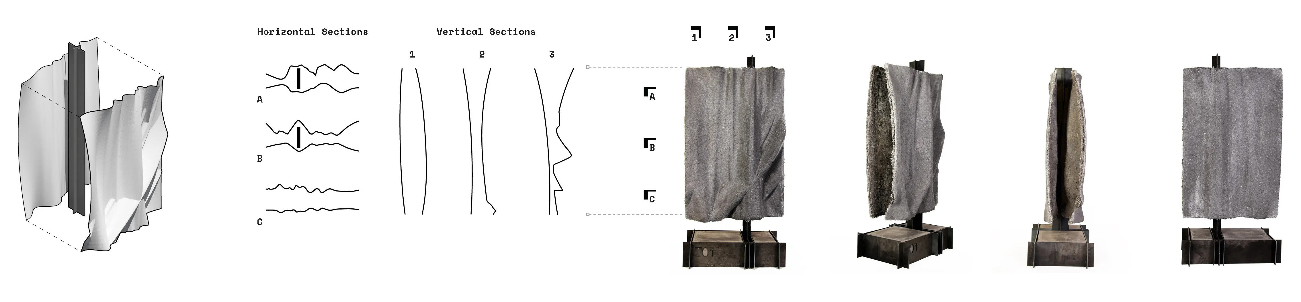
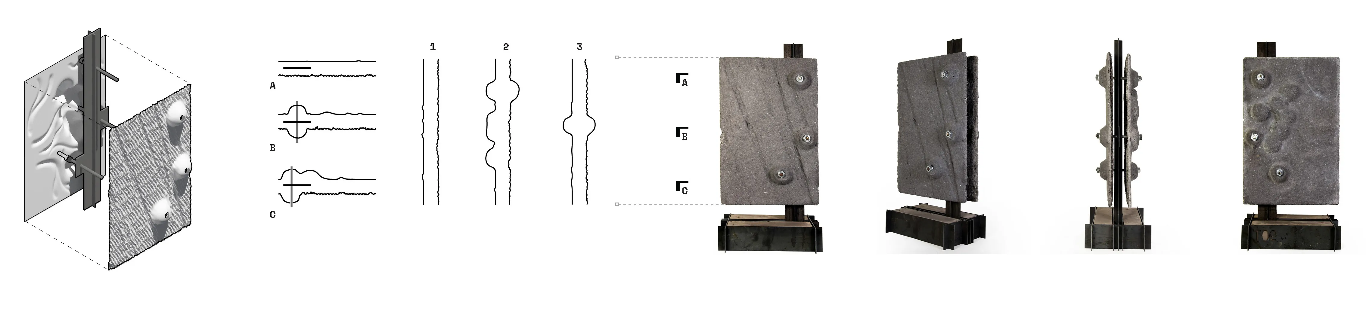
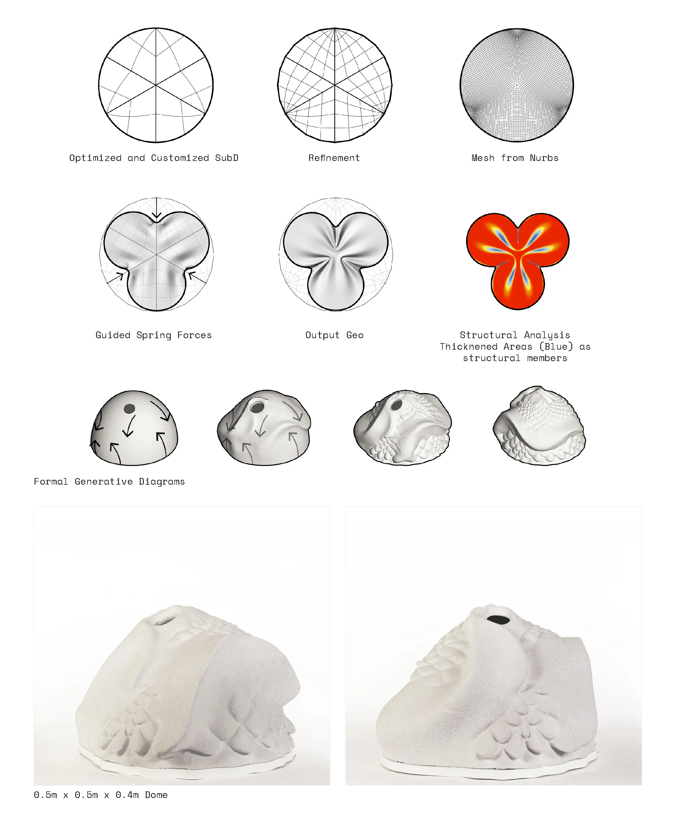
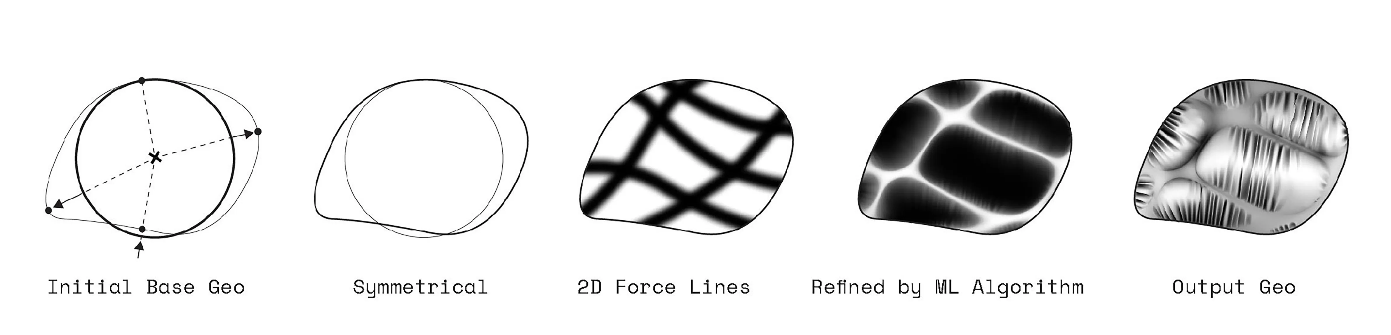
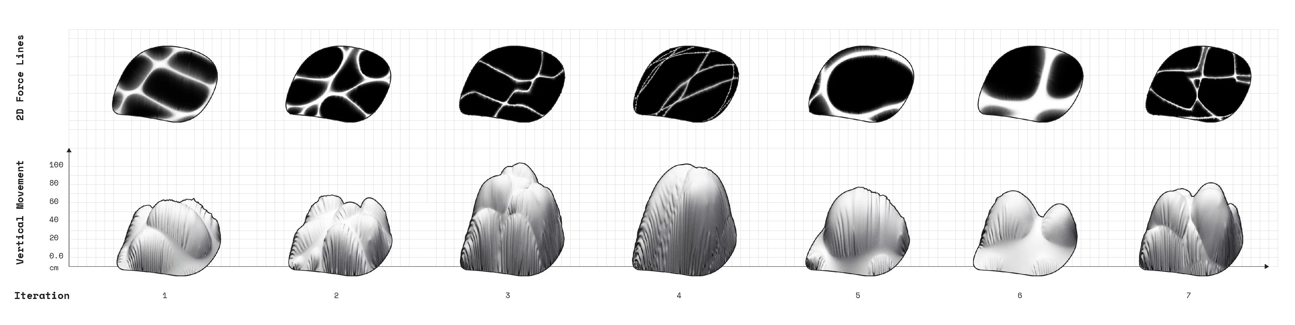
Investigating the relationship between embedded mathematical inputs and visualization structures to guide multi-dimensional behavior on rigid surface architecture.
Here, a disected circular surface form is re-shaped into custom subdivisons to allow for central forces to destort and transform is form into a pinch like structure with ribs as structural elements around the folded areas.
The rich text element allows you to create and format headings, paragraphs, blockquotes, images, and video all in one place instead of having to add and format them individually. Just double-click and easily create content.
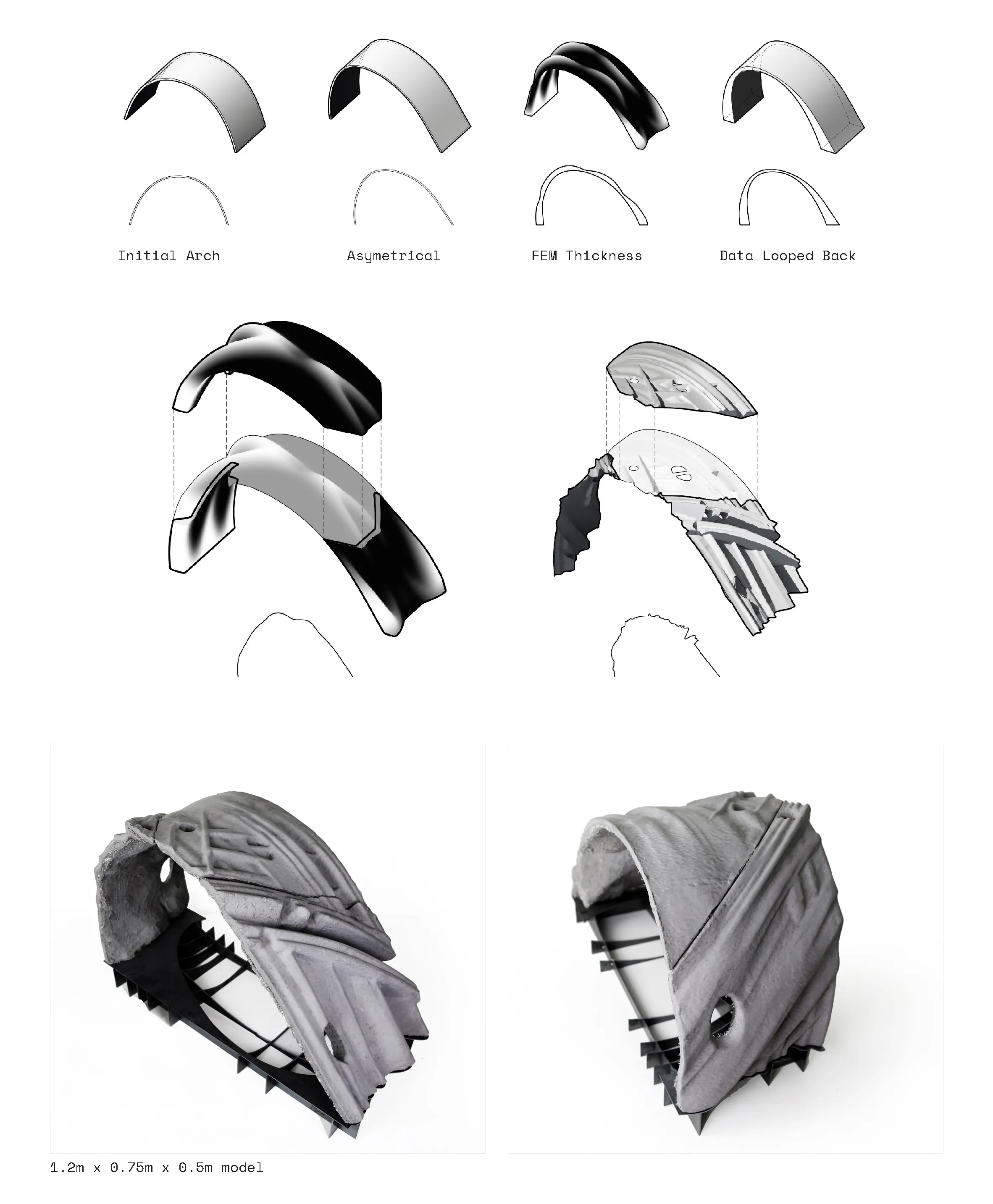
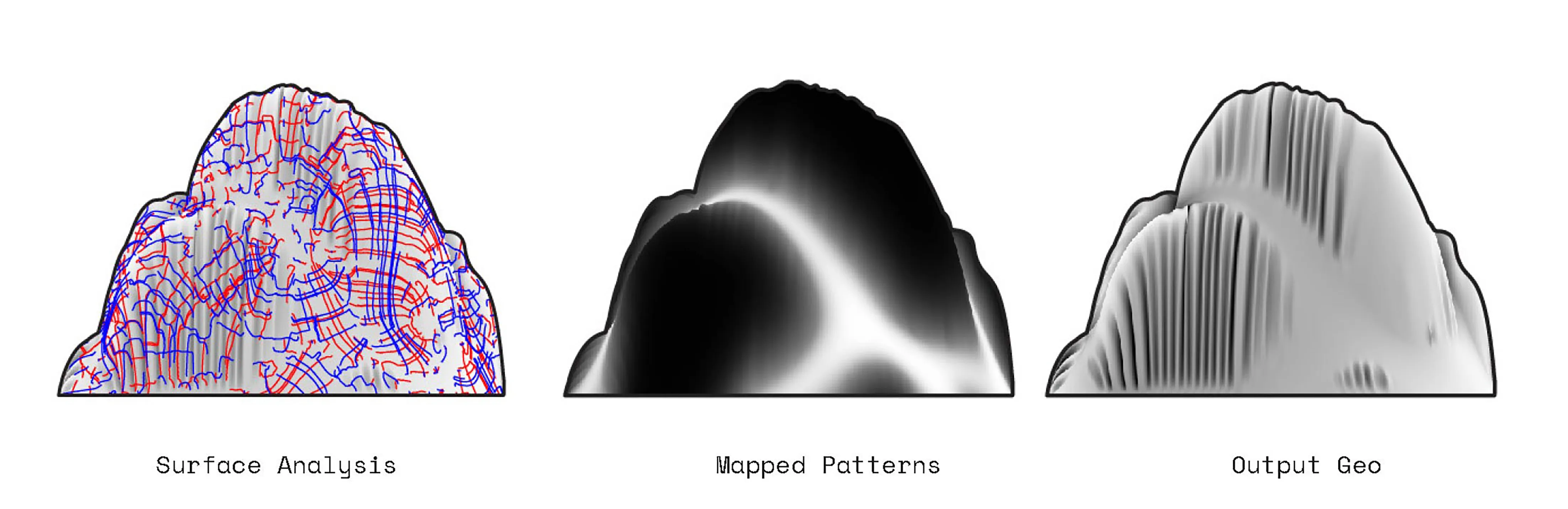
Surface undulations translated into a curved arch. Stress and Strain analysis were tested. The resultant ideal thicknesses were then translated into ribbed textures with depths corresponding to required forces.
Scaling the system in study 3 of double shell assemblies on a double curved surface with a sharp overhang.
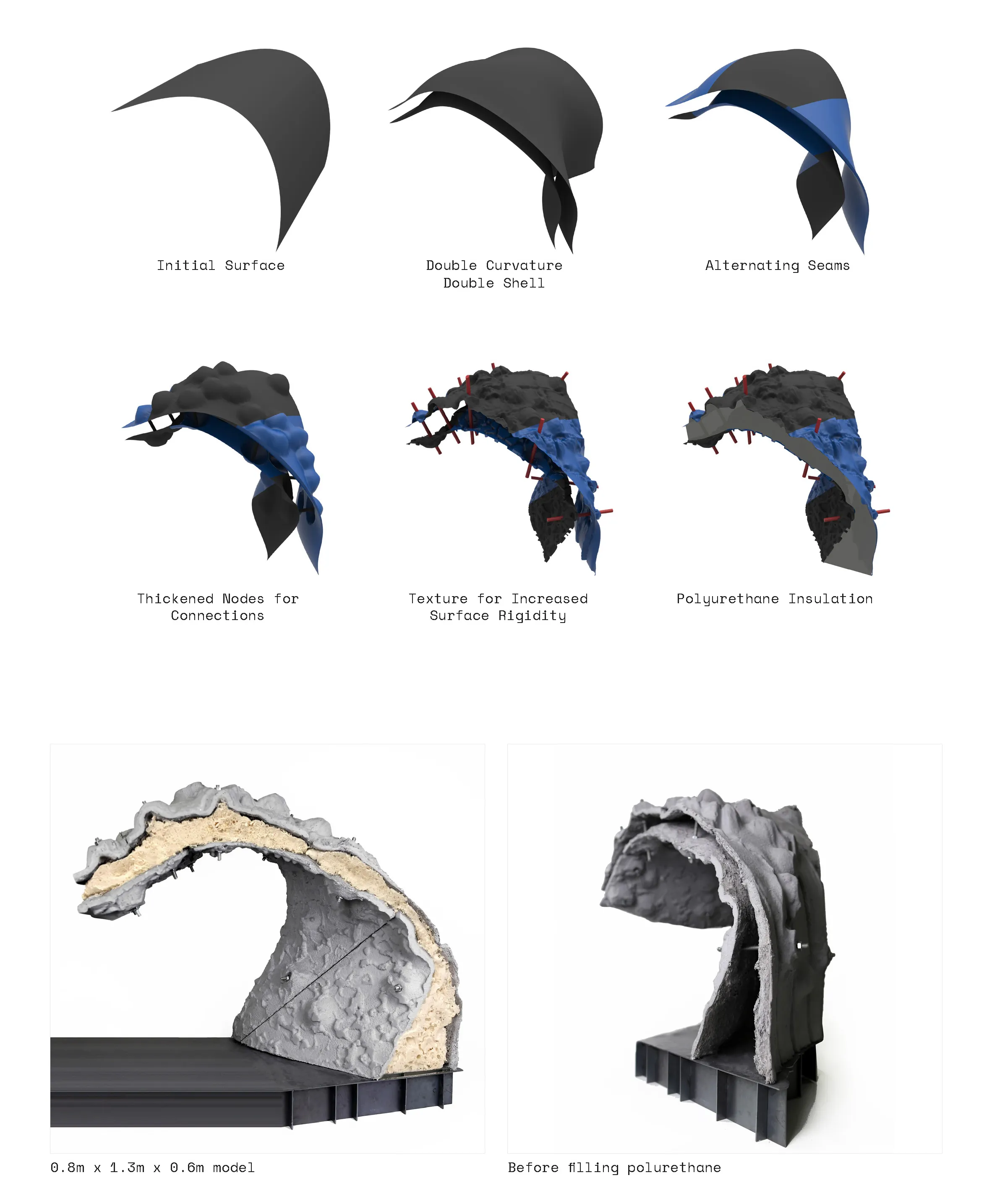
A computational feedback loop between 2D patterns that are translated into vertical projections. The 2D patterns are generatively created by indicating factors such as density, thicnkess and distance between
lines. Those three main factors compute the vertical growth as well as the second layer or ribs that are a result of the fabric material qualities that are fed into the physics engine.
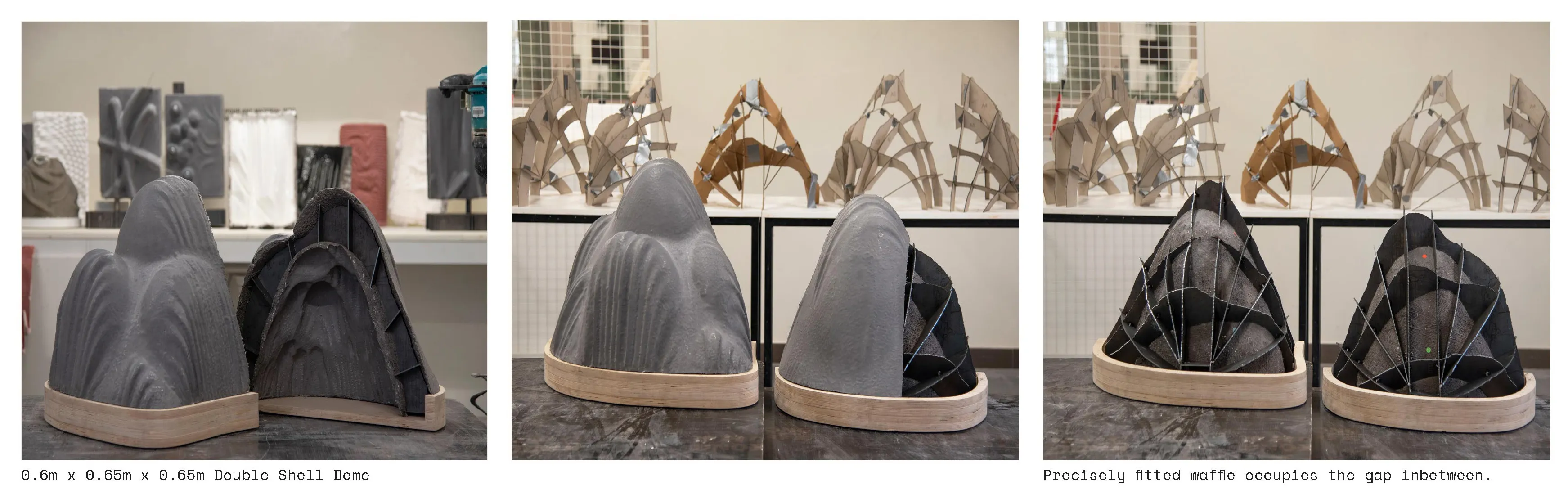
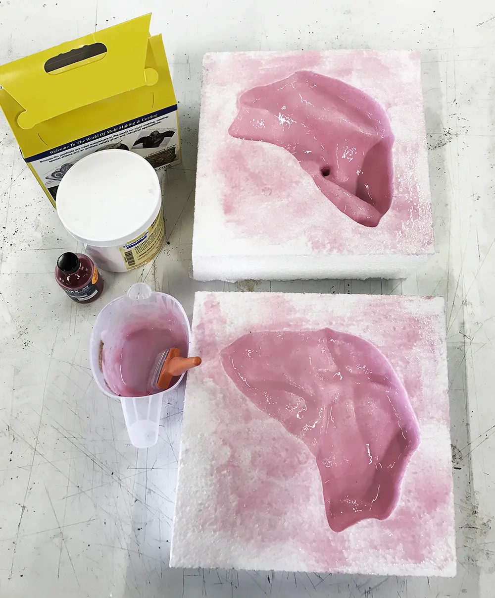
GFRC, multi-part molds, mold treatment, spray gun, compressed air, and safety tools.